Experimenting with Magnetic Loop Antennas
|
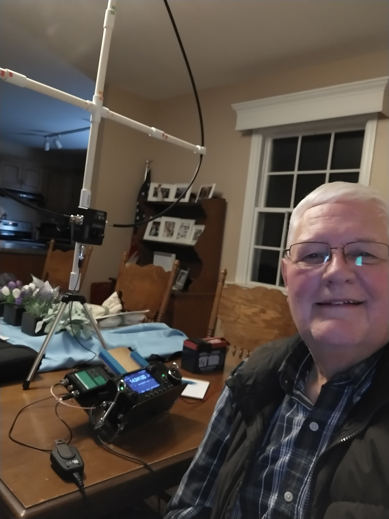
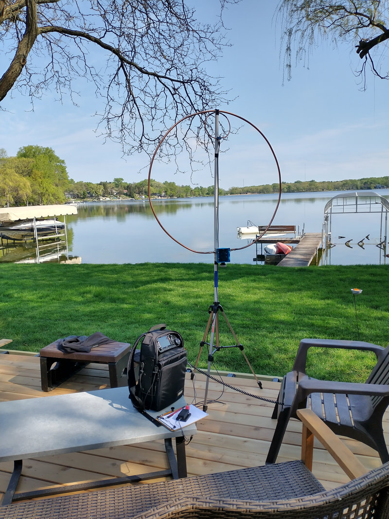
2022-04-25 While my wife was at a meeting at church I commandeered the dining table and set up my ic705 based pedestrian mobile rig and my SignaLoop mag loop. Made 4 contacts, including one SSB on 20m with AB2SG in K-1214 Cheyenne Mountain State Park in western CO and one 20m CW contact 1688 miles northwest with VE7QH at VE-5496 Aldergrove Regional Park in western British Columbia! I'm in southeastern Wisconsin. Three of the four were at 5 watts. I was trying out the little tabletop tripod I found at a thrift store recently. Was a bit top heavy but worked! Fun evening. Yes, I did restore the table before she got home!
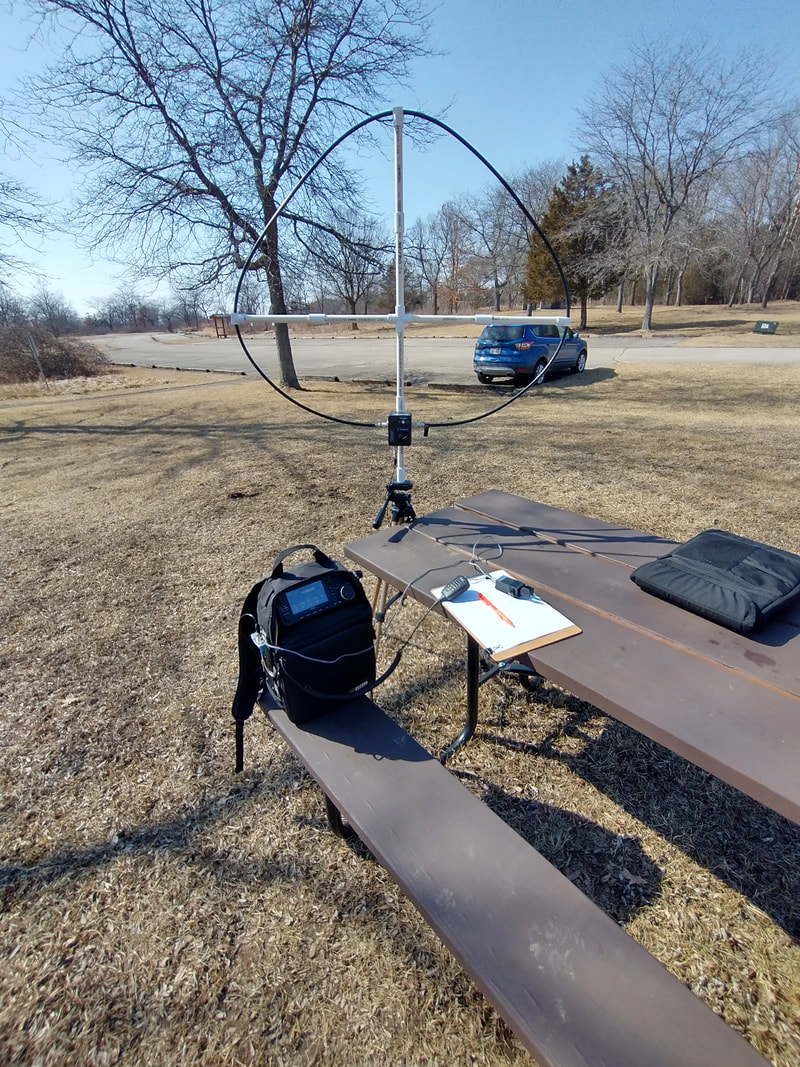
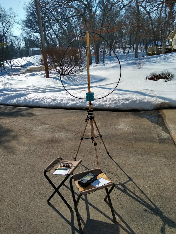
2022-03-16 Yesterday I decided to do a POTA activation at nearby k-4265 using my ic705 and the SignaLoop mag loop antenna. The setup is pictured below. I was successful on 20 meters logging 17 contacts, two being SSB, the rest CW. I wanted to try 40 and 30 meters as well. But I was unable to find the resonant point on the loop capacitor. My normal approach is to adjust the capacitor for maximum band noise and then tweak it watching the power meter on the radio. That worked for 20 meters quite easily. But I simply could not find a noise peak on either 40 nor 20 meters!
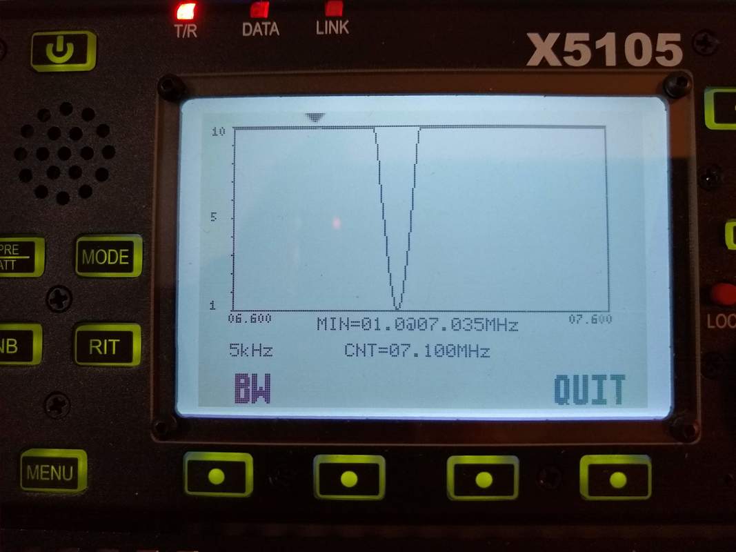
Thinking about that, I decided to set it up in my shack and play around with it. Of course, as it often happens, the noise peak was obvious here! Not sure how to explain that, but be that as it may, the thought occurred to me to turn the power down to near zero and then watch the SWR meter on the radio as I adjusted the capacitor. THAT seemed to work very well. The SWR dip was very obvious and when I turned the power back up the antenna was right on! So that may be my new approach!
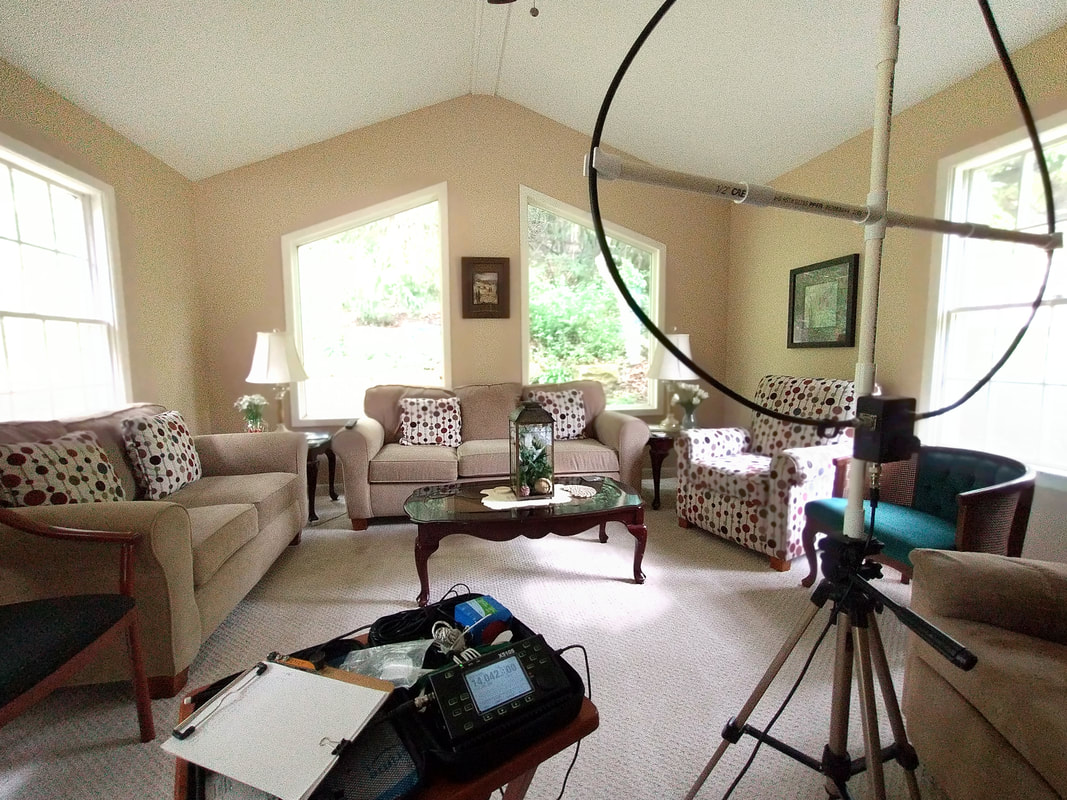
2021-08-07 It's hot and sweaty outside here in SE Wisconsin this afternoon. So I decided to assemble my SignaLoop mag loop, connect it to my QRP xiegu x5105 in the living room and see what would happen. To my surprise, within about two minutes I had two contacts with NA CW contest operators on 20 meters. Came back about half hour later and in five minutes got two more! Those guys push my CW skills with their speed. But the exchanges are short so I survived! I didn't really expect much from the antenna today. But now I'm "into" mag loops again!
2021-05-28 Today was "cold" and rainy, in the 40s. Not a good day to a park. But I just couldn't NOT play with my latest POTA antenna candidate, a SignaLoop magnetic loop. The POTA connection for me is that both my motivation and opportunity to operate portable is POTA. And making activations simpler and easier is part of that.
So this afternoon I set it up in our living room and connected it to my ICOM IC-705 POTA kit with a 6ft length of RG-58 coax. Bands all seemed kind of weak, at least on that setup. But after about 3pm CDT I began hearing a few signals. Finally got a solid 559 CW QSO with a station in Arkansas, 450 miles south on 20 meters. That was followed by a 559 my end, 339 his end, 40 meter QSO with one 250 miles southeast in Central Indiana. That one lasted just under 15 minutes, sort of a rag chew.
I was pleased with both. Whatever else they tell me, they indicate that the antenna does radiate fairly well. Even under less than ideal circumstances.
It'll take a few more QSOs to decide whether the SignaLoop works well enough to consider a primary POTA antenna.
2021-05-24a Tonight I went hunting with my new SignaLoop Portable Magnetic Loop. I'd been trying on and off all day but conditions simply did not seem good at all. But this evening 20, 30 and 40 had quite a few signals including two POTA activators, K4NYM and K5TER. With limited expectations I gave them both a call. Rig was my ic705 at 10w. They both came back to me! My signal wasn't overwhelming but it worked. I also had about a 10 min QSO with K4QZB in Alabama.
I don't think this loop is quite as good as my DIY one but it covers all bands from 80 through 17 meters. But most importantly (since it seems to work!) is that it can be broken down into a small bag about one foot square for transport and then quickly assembled on site. THAT can't be done with my solid copper one. Time will tell, but I'm encouraged. My main objective was to have a practical magnetic loop for POTA Activations.
I don't think this loop is quite as good as my DIY one but it covers all bands from 80 through 17 meters. But most importantly (since it seems to work!) is that it can be broken down into a small bag about one foot square for transport and then quickly assembled on site. THAT can't be done with my solid copper one. Time will tell, but I'm encouraged. My main objective was to have a practical magnetic loop for POTA Activations.
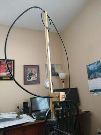
2021-05-24 As I think I've stated several times, the primary negative thing about my DIY mag loop is its rigid structure which makes it somewhat difficult to transport. I've been pretty happy with it's performance, so much so that I've begun to think of it as a primary antenna, not just a functional novelty. But on a quest for a bit more portable loop I recently ran across the SignaLoop Portable HF Magnetic Loop sold by Antanna4Less. It arrived today so I was anxious to play with it.
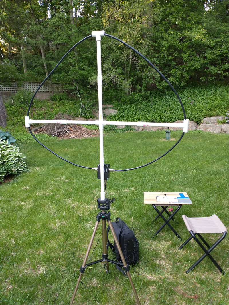
After assembling it which simply involved fitting the PVC frame pieces together, threading the coax through the T junctions at the ends of the spreaders and screwing the PL259 plugs on the ends of the coax onto the SO239 jacks on the tuning unit, I connected it up to my xiegu x5105 and quickly verified that it tunes up nicely 80, 60, 40, 30, 60 and 15 meters. The bands didn't seem very good today here in my shack with my G5RV or 40m EFHW but I took it outside to my open yard, connected it to my IC705 and tuned around. Again, no problem tuning it on any frequency. The few signals on 40, 30 and 20 peaked up nicely. But I couldn't raise anyone. Looking at RBN I never got it to register. But my portable EFHW also registered poorly so I think band conditions were a major factor.
Then I got the bright idea of setting it and my DIY loop up within arms reach from my left and the SignaLoop within arms reach to the right. I carefully tuned each of them to the exact same frequency and called CQ. Nothing, not even from RBN! I then tuned around and found a signal. Peaked both loops on it and listened carefully, one at a time. Clearly the DIY one heard the best but not by a whole bunch. Another observation was whether finding peak on a Field Strength meter or by watching SWR, The DIY loop was much fussier. Almost just looking it it would throw it off frequency while the SignaLoop was a bit more forgiving.
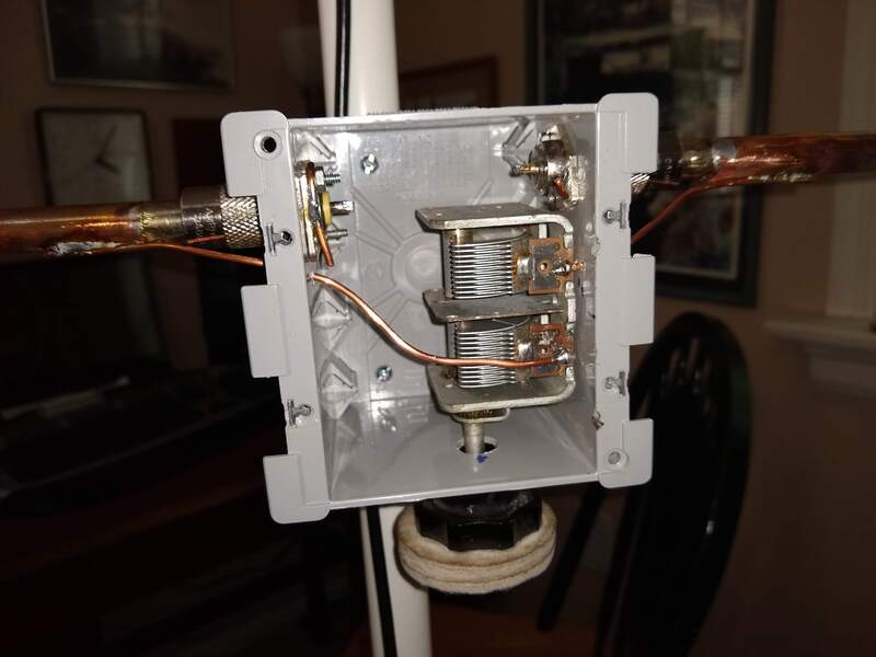
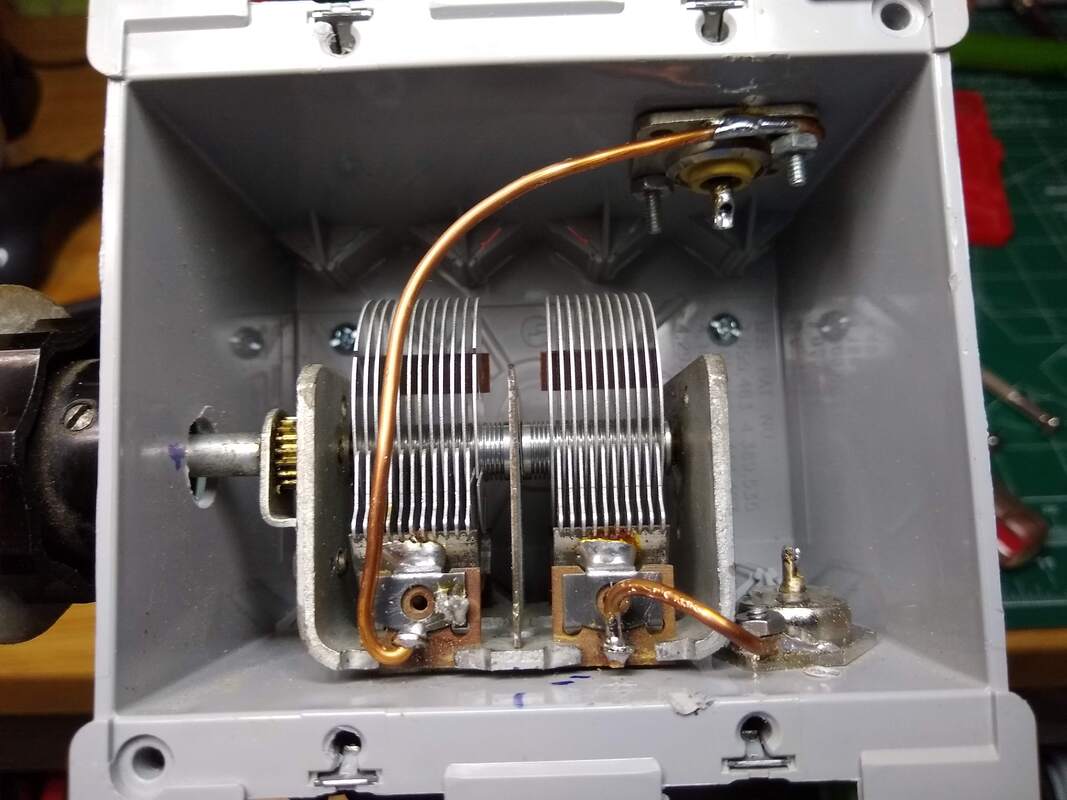
It then occurred to me that it would be interesting to look at the SWR sweep of them in this side by side configuration with my nanoVNA. The two photos below show the difference. The DIY curve is much sharper which I think indicates lower loop resistance and higher Q and likely more radiated signal. I need a little better day to make a final conclusion but I'm tempted to think the DIY loop is a better antenna because of lower resistance in the loop circuit. One final thought. I decided to remove the cover on the SignaLoop tuning box. It uses a toroid arrangement to couple to the loop rather than the driven loop my DIY uses. Second, it has a single gang capacitor meaning the signal has to go through the capacitor bearings. My DIY loop has a dual gang capacitor with one end of the loop connected to one stator section and the other end connected to the other stator section. They are electrically "connected" in series by the floating rotor, with no lossy bearings in the circuit. So it should be inherently less lossy, hence a higher Q. That's my theory!.
These are just observations. I want to give the SignaLoop opportunity to shine on a POTA Activation next time we get a good propagation day. I hope it's performance makes it worth using portable as it is a lot more portable friendly than my DIY loop.
2021-05-21 Today was an interesting POTA adventure. I have two state parks within about ten miles of me, K-4265 due east and K-1440 a little south and west. I activate both but K-4265 the most as it is a bit quicker to get to.
But today I decided to do K-1440. Unfortunately just as I took my IC-705 and DIY mag loop to the picnic table, it started sprinkling, then a light rain! So, since the weather map showed the main rain to the west, I decided to drive the 20 miles east to K-4265. Picked my picnic table, set up and started out on 20 meters CW and in 20 minutes I had ten in the log including one p2p.
Switched to 30 meters and in the next 24 minutes had another eight in the log. Then it started sprinkling! I had trouble finding a free frequency on 30 meters and towards the end propagation must have been shifting as both I and my hunters began having QRM. Thanks so much to you eighteen hunters who filled my log sheet.
The DIY mag loop is about to become my favorite antenna! It is so quick and easy to set up and change bands. Furthermore, the more I use it the better I get at tweaking it for best match.
2021-05-17 Spent the weekend in MN at my son's place for our granddaughter's college graduations. And along with all the other festivities, I found a couple opportunities to play radio with my IC-705 and DIY mag loop.
As the photo shows I set it up on their deck facing the lake. The first day managed one contact with a station in Texas on 20 meters. Next day had two contacts on 40 meters. All were CW at 10 watts. I'm sure I could have had more but didn't want to spend much time away from the family. The main point was just to use the mag loop in another setting, continuing to convince me that it is capable of being a first-choice portable antenna. I'm getting there!
|
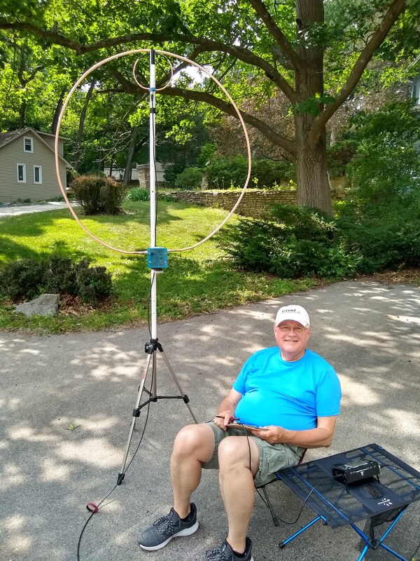
2021-05-12 Today was again so nice that I took my DIY mag loop to the front yard, set it and my Xiegu X5105 and it up on the sidewalk and proceeded to hunt around. The few stations I heard couldn't hear me. I called CQ SKCC on 40m and just CQ on 14.060, the QRP calling frequency. I was just about to give up when I switched to 30m and tuned around. WX4TX in NC was calling CQ. He was very faint but I decided to give him a shout as my last resort. Amazingly he heard me, not well but we finally got our calls through. He gave me a 119 and I gave him a 529. He was running 100w, I 5w. I don't know what his antenna was. But we did it! One is better than none so I packed up for the day! The setup is pictured at right.
2021-05-11 Well, though I feel like I am abandoning my kids, I broke down and ordered a commercially made magnetic loop. My excuse was, though I think my beautiful DIY one made with copper tubing performs as well or better than any I might buy, it is not at all convenient to take portable as it is rigid and awkward to to transport. After looking at many of them, all priced into the hundreds of dollars I decided on a signalLoop model HF-319 Portable HF Magnetic Loop Antenna. I admit the main reason was the price! But I did read all the reviews I could find on it and few if any were negative so I feel safe.
I am curious about how they connect the feedline to the loop. All my DIY experiments have been done with a small loop. I've seen several different approaches but none that I can imagine inside the small box along with the capacitor.
|
So after the warrantee expires (or before) I may see if I can get inside that box and investigate. Two I can imagine are 1) a winding around the main loop, 2) a toroid around the main loop with the driven winding also on the toroid. In any case I am anxious to try a POTA activation with some magnetic loop.
2021-05-10 Couldn't go to a park again today so decided to set up my ic705 to my DIY 1 meter mag loop and see if it might be a candidate for POTA. Managed 3 contacts, one, POTA activator BIL BROWN, K4NYM on 20m. 1082 miles. The other 2 were in TN on 40m. All CW. On my next trip to a park I think I'll take the loop. Always amazed it works at all! (the setup was similar to that pictured above only with the IC705.)
2021-03-19 Due to other responsibilities I wasn't able to activate a park today even though my wife and I did drive through K-0986 Chain-O-Lakes State Park in Illinois a short distance from our place in Wisconsin. I'll be back to activate it soon!
But mid afternoon I did get my ic-705 out along with my DIY mag loop which has been hanging on the wall as a decoration for many months. And I was pleasantly reminded again that it is a good antenna! In about 35 minutes I had five CW contacts, one on 40 meters and four on 20 meters. Two of them were POTA activators. One was in Florida, 1068 miles and another was in New Mexico, 1154 miles.
I was particularly happy how easy it was to tune the antenna with the ic-705. The noise peak was easy to hear and the SWR reading responded smoothly to fine tuning. I simply had no trouble. Now I'll have to take it out and activate with it! Too many antenna options!
2020-08-27 Tonight 40 meters seemed pretty solid and quite busy. I worked several POTA stations using my MFJ 40-10 EFHW Inverted Vee. Since signals were strong I decided to hook up my mag loop which has just been sitting in the corner for quite a while now. I was amazed how easily it tuned and how strong signals were. Ended up working two stations on CW, one in Kansas, 400 miles, and one in Maryland, 650 miles. Both were solid QSOs with me getting 559s and giving 569s. I rag chewed just over ten minutes with the Maryland station. The antenna was just sitting on the tripod about four feet away in my shack. So that was fun! The only "negative" with it tonight was the need to tweak the tuning and aim it. It would be a challenge to use if regularly when you want to tune around and work stations all over the place. But that is just how it works!
2020-07-19 Worked several RTTY stations last evening on 40 meters with my 1 meter copper mag loop. Rig was my G90 at 10 watts output. Several others apparently couldn't hear me on it but responded when I used my EFHW inverted vee. Received signal levels were very similar on both antennas. The loop was set up inside near my operating position as shown in the photo below.
2020-06-30a I can't seem to let this thing be! This morning I took it back to my garage shop and added a third strand of 12 gauge wire between each of the two sections of the capacitor and the ends of the main loop. It didn't harm it, at least as it still tunes all bands from 40 through 10. And I managed one sketchy contact with a POTA station just under 200 miles south east in Indiana. I say sketchy. He gave me a 559 and he was 579 to 579.
The sketchy part is that this antenna picks up noise. My noise floor was about S5. If I switch to my G5RV or my EFHW, it drops to about S2. Rotating the loop I also notice that the noise rises and falls but is always higher than on either of the other two antennas. I suppose having it inside at floor level could be a factor. Both other antennas are outside and away from the house.
The encouraging thing is that signal levels themselves are noticeably different from the variation on either of the other two antennas. No two antennas hear exactly the same due to height, orientation and inherent characteristics of each one. I feel like this one is no exception. That is a pleasant surprise. That was NOT true of it when the loops were both made of coax. Clearly the copper tubing enhances the antenna considerably. My most distant contact, 2100 miles, was with one of my earliest, coax versions and at 5 watts. And 5 of my five 1000 mile plus contacts were with the same setup. It wasn't during solar maximum either!
When I post about my experience on Facebook I get many comments such as this one, "Everything works better than a loop but a loop will work when nothing else will." Another guy wrote, "Its a compromise antenna (at best )." My thought is that every antenna is a compromise in one or more ways compared with some other one. I don't think I want to have a loop as my only antenna if I have any options but as I play with it more I see it as a valid option, particularly if you are in a very space-limited situation. I think a single band dipole, or an end fed half wave will likely always be a little better. But they are not feasible if you don't have the space or situation to deploy them. I feel the same way about verticals in general. But I've learned that they have their place and in that place are great antennas. That is how I am becoming to think about a well built magnetic loop. And even a not-so-well built one can serve
2020-06-30 I just did a bit of SWR testing. I can actually tune it up through 10 meters. The SWR appears touchy but I think I just realized it's due to RF in the shack on the higher frequencies. I'm guessing if I could get the antenna 20 feet from my transmitter it would show the same near 1:1 SWR as on the bands up through 15 meters. Discovered that accidentally last night when I noticed that the SWR changed wildly when I rotated the thing. Don't see the same or as dramatically on 15 and below.
2020-06-29 My DIY 1 meter diameter mag loop made with 1/2" copper tubing is gaining my respect. Thunder storms were traversing our area for several hours this evening. I didn't dare use my outside antennas. So I connected my loop up to my g90, just barely in reach across the room.
To my surprise there were good signals on 20, 30 and 40. I worked two CW stations on 40 and one on 30 meters! Solid 559 reports. The 30m chat lasted 22 minutes and at 716 miles was the most distant.
Perhaps this is indeed a real antenna?
2020-06-26 This is it! I added another 12 gauge link between each capacitor section and its respective end of the main loop. The intent is to further reduce loss by doubling the current handling capacity of the links. I also expanded the solder area where the links connect to the capacitor itself.
2020-06-25 I keep thinking I'm done with this thing and then think of one more "improvement!" This improvement connecting the main loop to the capacitor by soldering a short 12 gauge wire link between each end of the loop and it's respective capacitor section as shown in photo B. Photo A shows how I had it connected previously so the the PL-259/SO239 provided the connection to the loop. Potentially that PL259/SO239 connection introduced some loss which hopefully the direct solder connection reduces. The PL259/SO239s now simply provides physical mounting of the loop to the capacitor enclosure.
Is it better? I really have no way to tell. I'm listening to it right now on 40 meters and pleased with how it appears to be hearing on this pretty much dead band comparing to my EFHW. The other observation I have is that it seems to be even narrower than previously. If indeed I reduced some loss that should be one result. Time will tell.
2020-06-21 I know it's Fathers Day but I just couldn't resist playing with this loop again after church and while the beef roast is cooking! I'm increasingly impressed. Huge difference in performance since I switched from coax to copper tubing for the loop. Before I saw it as an interesting novelty that works. Now I see it as a competitive real antenna! I just had another QSO with it sitting on the floor in my ham shack. Comparing signals on it with the same ones on my EFHW and G5RV I'm surprised at the small difference in readings! Yes, normally one of the others will do better but the difference is on the order of an S unit or so and I can hear almost any signal on it that I can hear on one of the others! I still have pretty limited evidence to base that on but as an initial observation.... I'm surprised!
2020-05-20a Some ham shacks are more "open" than others. Today's was pretty open. I was sitting in the shade of a big hickory tree beside our garage with my x5105 and newly modified mag loop. The loop is 1 meter in diameter and is made from 1/2" copper tubing with the driven loop from 1/4" copper tubing. It seems to work quite well. I had three contacts with it this afternoon. Two on 40 and one on 20, all CW.
One trick I learned is that if you reduce the power to 1 watt it is easy to tune the loop as you avoid the Rig's SWR kick-back. A magnetic loop is very very narrow banded so finding the minimum SWR point can be tricky, especially if the SWR protection cuts the power. Limiting the power to 1 watt avoids that so the only fluctuation on the SWR indicator is from the antenna itself.
2020-06-20 OK, one more "improvement!" I've been worried about how fragile the attachment to the BNC connector is. Especially where it's soldered to the little center pin. It wouldn't take much to break that pin off, then the whole thing would be dead! I had seen a couple guys in videos use epoxy to to encapsulate their connectors. So I did that. I'm not happy with the result cosmetically at all. The biggest problem is that it is impossible to get form made with painter's tape off the epoxy! But it still works with no noticeable change. So I'm happy.😁😁😁
2020-06-19a I think I'm at a stopping point now with my 1 meter mag loop made with 1/2" copper tubing and a 24" driven loop made with 1/4" copper tubing. I've soldered all connections other than using PL-259 and SO-239 connectors to attach the main loop to the capacitor. I have a 1:! SWR on 40-12 meters and it will not quite tune ten metres.Everything is reasonably robust so I think I can move it around fairly easily.
I had one 40 meter CW contact with it tonight. The station was a little over 300 miles away and was running 100 watts to a dipole up about 50 feet. I was running 15 watts with the loop on the floor in the middle of the room. He gave me a 559 and he was a 579 in here.
I'm satisfied for now and will use it a while before contemplating any further "improvements!".
I'm satisfied for now and will use it a while before contemplating any further "improvements!".
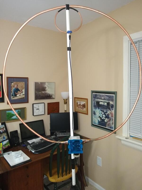
2020-06-19 So, how do you connect a copper tube/pipe main loop to the capacitor box? I got a ten foot piece of 1/2 copper tubing at our local home store. After much fussing I managed to solder the outer shell of PL-259 connectors on each end. Then I attached it to my capacitor box in place of the RG-8 sized ten foot piece of coax I have been using. Both are pictured below. Everything is the same with both loops as far as the capacitor, driven loop, etc.
The copper loop resonates almost identically with the coax loop with a couple exceptions. The SWR is somewhat higher with the copper loop, the exact opposite of what I was hoping for! With the coax I can get 1:1 almost everywhere. With the copper one I can get near 1:1 on 40m but am lucky to get below 2:1 on 20 meters. Also, with the coax the adjustment for lowest SWR and peak output on my Field Strength Meter is easy to find and is a nice clean adjustment. On the copper loop it's jumpy and somewhat more difficult.
I suppose one possibility is that the Q on the copper loop is so much higher than on the coax loop that the capacitor adjustment is simply more delicate.
Another possibility is that the higher SWR might mean that my solder job on the PL-259s is not all that good and there is loss. That got me wondering how others are connecting their copper loop to the capacitor? Not sure how to proceed!
A third possibility is that my driven loop size may be off which with a higher Q in the main loop is now becoming the "limiting" factor. My current one is 22" circumference. It should be 24". That may be my next step. I did buy some 1/4 copper tubing just for that purpose.
|
2020-06-18 I posted about yesterday's experience with the loop on the Facebook Mag Loop Group. One comment was that I should solder the capacitor wires to the SO-209 connectors. So tonight I did that. My initial observation is that it is an improvement. I can get 1:1 SWR on 40, 30, 20, 15 and 17 meters now and the dip seems much cleaner and sharper. That may be wishful thinking but I hope not.
Empirically, I quickly made one solid contact with W8HOG 330 miles southeast on 40 meters with it. He gave me a 559 and he was 569 in here. I was again using my G90 set at 10 watts with the antenna sitting in the middle of the room again. After the QSO was over he was still calling CQ so I switch to my MFJ EFHW inverted vee. He was consistently about one S unit stronger on the EFHW. That is encouraging.
I just tuned up on 20 meters and worked AG5Z in MS on USB, 789 miles. He gave me a 59 and was 57 here. He was running a magnificent antenna and a KW so he was doing the heavy lifting. I was 20 watts. I was broadside to his antenna when he heard and answered me. This darned thing works!
|
Earlier in the year I pretty much gave up on the magnetic loop. It just didn't seem to get through very well. Now, after fiddling with it again and making these improvements I'm a bit more optimistic about it.
My next improvement may be to replace the driving loop coax with something a bit better. Not sure if I'll attack the main loop with copper pipe or not though I'm guessing it would improve it. My two hesitancies are, 1) the difficult of simply making the loop, and 2) how to actually connect it to the capacitor. Would the improvement be worth the trouble?
2020-06-17 Today, after reading a couple posts about mag loops I decided to get DIY one out again. It's been sitting in a corner disassembled since January 6th. Two things bothered me about from its very beginning. 1) the wire I used to connect the capacitor to the main loop was quite small, a potential source for loss. 2) the driven loop was also of pretty small wire and I wasn't sure the diameter was right as the SWR was higher than it should be.
So, I rewired the capacitor with 12 gauge solid electrical wire. Then I found a 22 inch driven loop made from RG-58x that I had used with a smaller loop some time back. When I hung it in place and connected it up, the SWR was "perfect" on 20, 30 and 40 meters! It's below 1.5:1 up through ten meters.
But most surprising is that I had three QSOs with it! Two were SSB on 20 meters, one at 5w the other at 10w. The third QSO was on 40 meters CW at 5w. With band conditions being not-so-good the past few days I really didn't expect any contacts, I just wanted to check it out.
I have to keep the power around 10w or less as more will cause the capacitor to arc! It's just a capacitor from some old tube type broadcast receiver I found at a ham fest.
I have to keep the power around 10w or less as more will cause the capacitor to arc! It's just a capacitor from some old tube type broadcast receiver I found at a ham fest.
I guess I'll have to keep the thing out of the corner. Oh, did I say that it was sitting on a camera stand in the middle of my ground floor ham shack?
2020-01-06 The graphs and data below are a comparison of the three magnetic loop setups.
- My one-meter Mag Loop with an 8-118pf variable capacitor that requires an external capacitor to resonate it on 40 meters.
- The One-meter magnetic loop that I rebuilt using a 7-195pf variable Capacitor which tunes from below 40 meters through 10 meters.
- And finally the 7-195pf variable cap with a 1.4-meter magnetic loop.
The 1.4-meter loop will resonate from about 5.5mhz to about 22.5 mhz. SWR on the 15 meter band is about 3:1 or higher so it really isn't very useful on that band. Its 2:1 or lower on twelve meters and just a bit lower on 20 meters. I can't speak to its comparative effectiveness as an antenna though I did have one CW 40 meter QSO with it and got a 559 report. He was 559 here too. My initial observation is that it's size is kind of inconvenient and it is probably best on 30 and 40 meters though perhaps usable on twenty. So though I'll do some more playing with it, I lean heavy toward the one-meter loop based on my experience with it so far.
2020-01-05 Today I installed the 7-165 pf variable capacitor I got at the hamfest yesterday in a box along SO239 jacks and connected the one meter loop to it. I made it as similar to the old box as i could so i would be able to switch between them. The new one resonates the loop from 6.7 mhz to 29.5 mhz.
The capacitor is a clean, unused dual gang capacitor. The two sections aren't quite identical. One measures 15-370 pf. The other 16-400 pf. When wired in series from stater to stater the capacitance is range 7-195 pf.
New capacitor installation on left, old capacitor installation on right.
Initial observations:
- The SWR is near 1:1 through 15 meters. It rises to about 2:1 on 12 meters and is 3:1 plus on 10 meters. clearly it is most suitable for 40-15 meters. Usable on 12 and likely unusable on ten meters. I guessing that is because of loop size.
- With the reduction gear drive it is much easier to tune than the older direct drive one.
- Somewhere between 10 and 20 watts it arcs.
- By far the easiest way to tune it is by watching the noise level on the waterfall display of the G90. Seldom does it need tweaking when set using that approach.
|
2020-01-05 Yesterday I went with a friend/neighbor/AF9L to a nearby hamfest. Among the three small purchases I found was an unused old dual section variable capacitor. It is dual section and with the two in series measures 7-195pf. The drive mechanism seems pretty smooth and everything is clean.
The plates are pretty close together so am not sure it will work for my mag loop, even at QRP power. But if so, a quick check of SWR indicates it will tune my loop from above ten meters to below 40 meters. And that without needing to add an external fixed capacitor as with my current one. The prospect of that plus the reduction gear made the $5 risk seem worth it! Now to build the box with connectors, etc. and see how it plays.
All part of my ongoing hopeless addition to playing with antennas; mostly low cost, very light weight, easy to put into service and use ones suitable for portable use.
|
2019-12-19 Following is a perhaps helpful graph and data taken from the NanoVNA-Save software of my mag loop tuned to 40 meters.
2019-12-13 Today, after too-long a string of below-freezing temperatures it warmed up to 42. So quick, I grabbed my "new" one-meter mag loop, xiegu G90, Miady lifepo4 battery, straight key, mike and makeshift table and headed outside to operate portable in my driveway. My plan was to set up in the yard beside the house but the sun was already low enough in the southeast Wisconsin sky at 1:30pm to put the side yard in the shade of the house. So "driveway to the rescue!"
I had my phone and checked the POTA page but there were no current spots. My neighbor, AF9L had stopped by about noon and said that 20 meters was booming. But I heard little activity there. So I tuned down to 40 meters. It was pretty busy on CW and signals were strong. So I tweaked the antenna tuning and answered W3MWR's CQ SKCC on 7.054 from Pennsylvania. He was 579 and gave me a 559. After tuning around a bit I heard W8ARC in West Virginia calling CQ SKCC on 7.057. He came right back and we were both 559. Two good contacts in about 15 minutes.
By then it was getting chilly and signals seemed to have dropped way down or disappeared so I packed up and took the long 25-step trip up the driveway to the house! I was very pleased with the whole experience. Not quite a "wilderness" trip but all the gear worked. I especially liked that there was no push-up mast or counterpoises to mess with. Just assemble the antenna (actually I just carried it outside assembled!), connect the coax, key and battery and go! The experience wasn't long enough to say this but I think the loop works better outside. Even though it was only about 20 feet from my radio room where I've had most of my QSOs with it. Next time it warms up I may take the 1.4 meter loop outside and give it a go.
Conclusion? Portable opps in the winter in Wisconsin in the driveway with a magnetic loop is fun!
2019-12-10 Well, after playing with magnetic loops for quite a while and especially the past couple of weeks, I have some observations.
- First, they are not magical or complicated. They are very very simple, nothing more than a large main loop, resonated at the operating frequency with a variable capacitor connected to the two ends of the loop. There are various ways to connect it to your radio but one of the simplest ways to do that is a second loop (driven loop) with a circumference of approximately 1/5th that of the main loop. The deiven loop is placed near the main loop, usually at either the top or the bottom, opposite of the capacitor. That's it.
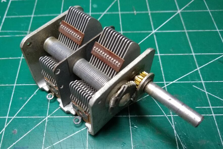
- The variable capacitor needs to meet three primary criteria. a) be of a capacitance that it can resonate your main loop at the frequency you desire. With a one-meter loop a tuning range of about 10pf to 200pf will be about right for 40-20 meters. b) be able to handle the high voltage that will be across it at resonance. I standard broadcast receiver type capacitor will work for power levels around 20 watts or less. c) offer the lowest conductive resistance possible to the loop to minimize losses. A typical way of handling that is to use a two ganged variable capacitor with one end of the main loop connected to one of the stators and the other to the other stator. The rotor then then "floats" electrically between the two capacitively coupling them. The result is no moving connections to get dirty and offer erratic or high resistance connections.
- Main loop diameter is important but not super critical to the performance. Typical loop diameters range from about 3 feet to maybe 4-1/2 feet. That is large enough to perform reasonably well from 40 meters up through 20 meters. But its not so large as to be unwieldy! You'll have to balance the diameter with the capacitance of the capacitor to get the tuning range you want. Larger is generally better to a point but is related to operating frequency. Check out this link for a simple calculator. http://www.66pacific.com/calculators/small-transmitting-loop-antenna-calculator.aspx.
- Main loop material. The primary concerns as far as what to use for the material for the main loop are loss and surface area. Both will be affected by the conductivity and cross section of the material. A larger cross section is generally better. Many loops you buy or that people make use RG8 or similar coax. Pay particular attention to the connectors as the connections between the loop and the capacitor are main resistance points. But don't be put off by that. I have used standard PL259 and SO239 connectors as have many others. Copper or aluminum is preferable to steel but both work.
- The driven loop circumference should be approximately 1/5th the circumference of the main loop. It's not super critical but deviating too far from that will result in higher SWR at resonance. Diameter of the wire or material from which the driven loop is made is not big concern. #14 or #12 electrical wire will work.
- Have at it! Try something. You can and will improve it as you gain experience! Just have fun with this novel antenna.
|
2019-12-10 OK, this morning I made a 3 ft diameter driven loop out of #14 electrical wire for the 1.4 meter diameter main loop. That solved the SWR problem. Now it is below 1.1:1 on 40, 30 and 20 meters. Question answered! Also if I plug my coax capacitor across the main tuning capacitor it will tune the whole 40 meter band! It even gives me a 1.6:1 SWR on 5.405 Mhz! I sort of hate to admit it, but this is fun!
|
SWR traces of a 1.4 meter magnetic loop for 40, 30 and 20 meters with an 11 inch driven loop.
|
2019-12-08 One of the responses on Facebook suggested a 1.5 or even 1.7 meter diameter loop for 40 meters. I was just about to cut a piece of RG8 coax to that length when I discovered I had a 4.3 meter (14 ft) length with connectors hanging on a peg in my garage! That would result in a 1.4 meter diameter loop, so I did a quick modification to the center pole allowing me to mount the capacitor box lower and thus accommodate the larger loop! Then I quickly checked to see if it would tune. Low and behold, it does, with just the 10-120pf variable capacitor it will tune from 7.100 mhz to 14.250 mhz. However the SWR is not as good as with the 1 meter loop! I'm wondering whether that is related to the size of the driven loop? At 1/5th the circumference of the large loop it should be 0.8 meters or 2' 10" circumference or 1' 5" diameter. It is now about six inch diameter. Always something to play with!
|
After writing the above I put the 1 meter loop back on the capacitor. One problem with the larger loop is that indoors it simply takes up too much space and is very difficult to rotate. Also, it won't quite tune down to the CW portion of the 40 meter band so requires I make another capacitor to put across the variable. I may at some point make a larger driving loop and play with the 1.4 meter one again but for now I want to just go back to what I know works well.
|
SWR traces of the one meter magnetic loop for 40, 30 and 20 meters with a 60-1/2 inch driven loop.
|
The three images at right show the SWR curves on the 1 meter loop for the three bands. One question I have shows up on the 20 meter trace where there is one "up-peak" on the left of the resonant frequency and two above that frequency. What are those?
|
2019-12-08 When I posted the latest version of the loop and the success I've had with it the past few days on Facebook a couple people raised concerns about possible negative health impact being so close to me while operating. Not sure how valid those concerns might be or exactly what one might do about that. Without a remotely tuned capacitor it has to be close enough to tune it to resonance on the desired frequency. I note that most of those you purchase have the same potential problem. Interesting issue.
|
Left: 1 meter loop. Right 1.4 meter loop.
|
2019-12-07 If you follow my activities at all you'll realize that for some strange reason I am "into" antennas. I'm constantly thinking about them, building them, buying them and putting them up and taking them down! I'm far from an expert but am gaining experience and maybe even knowledge about them. My article comparing various wire antennas is probably controversial but is how I'm thinking about them at the moment.
One that constantly messes with my mind is the magnetic loop. So yesterday I set it up and connected it to my antenna switch which allows me to quickly change antennas and rigs.
After the initial tune up for peak noise and running the obligatory SWR sweep on both my G90 and X5105, I cheated and tuned around 40 meters using my EFHW antenna. The band wasn't very exciting but suddenly K40Y popped up at 7.054 Mhz, just ending a QSO. He was 599+ on the EFHW. Switching quickly to the mag loop, peaking it and rotating it for strongest signal he was 579 to 589 on it. So I called him running 20 watts! That satisfied my short term craving so I disconnected and put it back in its place in my closet!
I was all excited when he came back until he gave my signal report, 339! I noticed that I my SWR was pretty high so I carefully peaked it for maximum power as indicated by me Field Strength Meter. He didn't comment but we completed the QSO with no trouble so he clearly heard me - hopefully better!
Then this morning, as I was writing this, I decided to give it another go, result? Three more 40 meters QSOs! Two with SKCC callers on CW and one SSB one with the MidCars Net Control on 7.258 Mhz in Indiana, KC9YTC. None were exotic DX but that's OK, it works!
All that to say, never give up on an antenna, particularly one that is somewhat unique. Though I'm convinced the loop doesn't rival the EFHW in performance, it does allow me to have an HF QSO without an outside antenna. That is something the EFHW can't do!
Further, even a compromise antenna can provide amazing results. I've now had a total of 43 QSOs with the mag loop since my first version back on December 18, 2018. Twenty nine of those were at 5 watts. And my current long distance record of 2118 miles with a station in Puerto Rico on 20 meters was at five watts. He gave me a 579!
|
2019-11-22a Later this evening I decided to mock up the "rectifier" approach I first thought of. The schematic is shown. It works. Better or worse? Not quite sure. I need to play with the values of both the resistor and capacitor and possibly the number of turns in the coil to really decide. Both approaches give a clear indication of peak current and resonance.
|
|
|
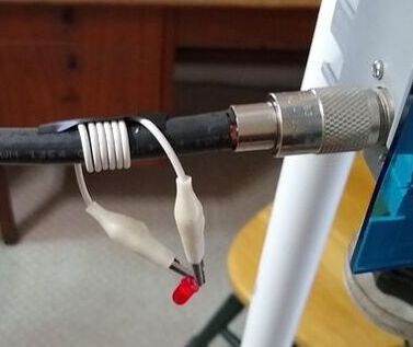
2019-11-22 One of the things I love about ham radio is the stimulation to think up and try new things. The picture at right is one of those. I posted to Facebook my comments below about use of a field strength meter to tune or peak my magnetic loop. In response a guy wrote, "I'd like to figure out how Alex does it with an LED on his Alextune."
That got me thinking, why not just wind a wire around the loop, put a diode in series with a capacitor to "ground", with a resistor in series with an LED across the capacitor. The diode and capacitor are a half wave rectifier and the voltage across the capacitor will be directly proportional to the RF current in the loop. The LED will glow brighter or dimmer based on that proportional voltage.
Then it hit me that an LED IS a diode! What would happen with just the coil and led? A short clip lead and old led
|
removed from something are a "breadboard" implementation of the idea. The exciting part is that it works! In fact it works well. With five watts from my G90 the LED lights with the peak is easy to determine. And the SWR meter on the radio says it is 1:1! Playing with a couple different LED's you may need to adjust the number of turns for different ones.
It can be cleaned up a bit but I think it is a functional concept and is easy to implement. So success! I can go eat breakfast now!
2019-11-19 Had another 40 meter QSO with the loop this evening with W5LNI in Arkansas, 533 miles. He was 579 in here and gave me a 559. Not half way around the world but still exciting! I found the quickest way to fine tune the loop after peaking it for maximum noise is to look at a field strength meter. When it peaks, the SWR will be as close to 1:1 as you can get. That seems easier to me than watching the SWR indicator on the radio. If the field strength meter is any indication of how tuning affects performance, having the antenna tuned "exactly" is really important. The peak is very sharp. I think it is sharper with the coax capacitor than with the ceramic ones I was using earlier.
SWR measurements taken on the magnetic loop following the QSO with W5LNI.
2019-11-17 0315Z Just made my first 40 meter contact with W3IDT (U 57 MDC) after rebuilding the mag loop using the 3' coax as the add on cap and threaded up center of mast. He was operating in the ARRL Sweekstakes. So at least I know it does work! Tuning is challenging. Need a geared down Cap! He didn't give me a signal report but judging by how many times I had to repeat I'm guessing I was about a 44. He was a solid 57 in here from Maryland, just over 600 miles. My loop was standing on the ground floor in my shack surrounded by walls and a 50' hill immediately behind the house in his direction. I'm guessing if I were outside it would make at least some difference. That's one contact each on 20 and 40 meters. Now to strike it rich on 30 meters! I was using a ten foot RG-174 feedline.
2019-11-16 Something got me thinking about my mag loop again the other day. Might have been a post in the mag loop group on Facebook. Anyway I decided to increase the diameter of my loop from it's current 33 inch diameter to one meter (39.4 inch) diameter, which seems to be what most pre-made ones are. The biggest hassle was putting the PL259 connectors on the 10'4" piece of RG-8 coax I cut to length. The connectors were the cheap nickle plated ones which don't solder worth a darn. But I finally got it. I also got a five foot length of 3/4 PVC to handle the larger loop.
I used the 12-123pf capacitor described below that I was using with the shorter loop. It would resonate on 10.15mhz (85pf) and on 14.15mhz (50pf) but not 7.15mhz which needs 175pf. I needed an additional 50pf to resonate on 40. With a bit of experimenting I found by connecting a 3 foot RG58 jumper across the variable capacitor I could resonate 40 meters nicely! I don't know how good of a capacitor an open ended piece of coax makes but the loop seems like it has a high Q with it. So at least temporarily I'm in business. By the way with the coaxial capacitor connected I have a capacitance range of 84pf to 195pf.
I couldn't wait to to give it a try so I tuned up on 20 meters I right away had a QSO with N6AR in Florida, just over 1000 miles south east of my residence in SE Wisconsin. He was 579 in here but was in a contest so was only giving out quick 599's. The loop was on the ground floor of our house surrounded by walls and all sorts of metal and electronic stuff. I know that isn't a very exhaustive or conclusive test, but I'm pleased. When I have more time I'll try more contacts on 20, 30 and 40 meters.
After completing the above it further occurred to me that I could make a cleaner and neater installation of the coax capacitor if I simply cut a 3 foot length of RG8X (which is what I had in bulk) and solder it to the little connector board I had made up instead of using the BNC connector. Then I wondered whether I could stick the "tail" of the piece of coax into the center of the support post. The picture above shows the result. As nearly as I can tell by measuring SWR with the tail hanging down vs. up through the center of the support post there is no difference. I'm sure this isn't my last modification but it's time to stop now!
2019-10-30 A few weeks back, playing with my mag loop I blew the capacitor that I add to the variable capacitor so it'll tune 40 meters by hitting it with too much power! I scrounged around and found a combination of junk box ones that work but decided to order some "proper" ones with high enough voltage rating that I wouldn't have a repeat performance. Well yesterday they came. Turns out they won't work. But the loop still works on 20 meters without the capacitor. Much to my surprise I was able to have a SSB QSO with the YL System operator on 14.332 mhz at 20 watts! He was in Florida. Actually I had two QSOs with him. The first one was using my MFJ EFHW antenna by accident since I failed to throw the switch to the mag loop! He gave me a 55 report. I immediately discovered my mistake, threw the switch and did a recheck using the loop. This time he gave me a 53 report. The band was up and down the whole time so the reports are not definitive. Never mind, it works! I had almost given up and forgotten about it while playing with wire antennas! Oh, and it rebooted one of my computers as well which was right in the radiating path and only a few feet away!
|
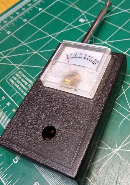
2019-05-20 This past week a friend, KD9KHI, and I attended the Dayton Hamvention. Amazing experience that every ham should attend at least once. Not sure I'll ever go again. We walked miles of flea market tables and booths as well as by nearly every vendor booth. Way too much! But one $6 purchase I made was worth the trip (well not really!). It was what I thought was an MFJ-801 Field Strength Meter. Turns out it was like a lot of my stuff, started out as the MFJ-801 but had been modified by a previous owner. I wasn't happy with the mod that guy did so did my own. Click here if interested in those details.
I mention this here because one of things I have wondered about my magnetic loop is it's radiation pattern and if one could use a field strength meter to tune it. I pretty much knew the answer to both questions but I like to "see" things for myself. So this morning I used my new field strength meter to do some experiments. First the tuning question. Using my Xiegu x5105 with the field strength meter about a yard away from the loop, I tuned, first listening on the receiver for peak noise, then watching the SWR meter on the radio I tweaked it for lowest SWR. As I expected, the field strength meter peaked right at the lowest SWR! Playing around I'm not convinced that using that peak output is as easy for peaking the antenna as the radio SWR meter, but it clearly works. The challenge is that the output curve is very sharp and the meter goes from peak to near zero very quickly. Perhaps increasing the size of the capacitor across the meter might help by slowing down the discharge rate of the capacitor? Not sure.
|
On the question of peak and null as the antenna is rotated, it appears very distinct using this little field strength meter. I'm sure my meter is not linear so my observation is not quantifiable. But The meter goes from near full scale to almost no movement at all as I rotate the antenna from inline with the meter to broadside to the meter. That does reasonably approximate my observations from listening to signals.
My conclusion is that a cheap and dirty signal strength meter is useful and well worth having in one's bag of tricks, particularly when playing with a magnetic loop antenna.
2019-05-11 A few weeks ago I took my magnetic loop outside and set up everything. but to my dismay, it would not tune on 40 meters. Thirty meters and above worked just fine. What could be wrong? That was the first time I had really tried to use it since inverting it as described below. It was chilly and I didn't want to mess with it so brought it in and stashed it out of the way, perhaps to be forgotten forever. But yesterday I decided to give it another chance.
I wasn't particularly happy with the thing inverted so decided to switch it back to the capacitor on the bottom, thinking that magically that might also cure my 40 meter problem. It didn't. Then it occurred to me that perhaps I had zapped the plug in capacitor which allowed it to tune 40 meters. A quick measurement confirmed that the capacitor was blown. Maybe there is something to that high voltage stuff! Bottom line, it's working again with a new capacitor. Actually the capacitor now consists of two 270pf capacitors in series, having the voltage across each.
2019-04-15 Yesterday in a Facebook Group focused on magnetic loops I read a discussion of where the capacitor and driven loop should be located on the main loop. Specifically should the capacitor be at the top or bottom and should the driven loop be opposite that. The "expert" in the discussion who apparently has been involved in commercial design of small magnetic loops argued, convincingly I might add, that the capacitor should be at the top and the driving loop at the bottom. Why, well the extremely high voltage across the capacitor should be as far from surrounding metal things as possible, including the coax that connects to the driven loop. Since most magnetic loop supports are metal and if the driven loop is at the top the coax usually drops right past the capacitor those two things reduce the effectiveness of the loop. He went so far as to say something like that such an arrangement significantly interferes with the loops performance and much of the "good" people attribute to it is likely from feedline radiation.
Whether he is right or wrong and if right just how significant that is I can't evaluate. But the design of my loop is such that it was very easy to flip-flop it, so I did. The left photo below show the rebuilt loop with the capacitor at the top and the driven loop at the bottom. Everything else is exactly the same as before. The other two photos show the SWR curve of the rebuilt loop on 40 and 20 meters respectively. I haven't had any QSOs with it and the band had almost no signals on it when I finished so I haven't' done any real evaluation of it beyond the SWR checks. The only two disadvantages I see with this new configuration are that it is now a bit top heavy and you have to stand up to tune it! Life is just filled with difficulties! :-)
|
2019-02-22 Today my rebuilt magnetic loop made it outside for the first time. Winter here in southeast Wisconsin has been close to brutal this year with temperatures dipping to minus 25f and wind chills down to around minus 65. And snow... We've had something approaching 40 inches so far! And some of that mixed with freezing rain and ice. Being outdoors was something to be minimized, certainly not played in by guys like me. So today's bright sun and temperature of plus 38 degrees inspired me to take my magnetic loop, Xiegu x5105 and straight key out and set up in the driveway and enjoy the warm sun while trying to make a contact or two.
The result? Well, not a suntan! But I did have one good 5 watt CW QSO with W5MIG 1040 miles southwest in Texas on 20 meters! I heard and called a number of other stations on 20, 30 and 40 meters but couldn't raise them. Very few were strong and the QSB was pretty bad even with the strong ones. But I was happy! With QRP one decides ahead of time to be happy with the results... to savor each contact.
I'm not sure if it was the antenna or what, but the atmospheric and other noise levels were very low on all of the bands. I think getting away from the house may have made a difference.
The low band noise also highlighted the antenna's rather narrow radiation pattern. It was obvious when you were pointing right at the transmitting station.
At the same time the low band noise made it a bit difficult to find the resonant point because there was little noise to peak when the antenna was tuned. On 30 meters I had to resort to decreasing the transmitter power to minimum and holding the key down while tuning the capacitor to even find the resonant point.
|
Even though I only had one QSO it was really fun to set up pretty much like I might in some more remote portable situation. I was surrounded by all the modern amenities but not connecrted to nor using them for that hour or so! That's portable isn't it?!
|
2019-02-17 I think I've actually completed the rebuild, including the jacks to plug in the 40 meter tuning capacitor and a cover for the electrical box. I made on e 40 meter QSO with it this afternoon during the DX contest with a CJ3A Islington Ontario, 473 miles north east of here. He was 589 and gave me a 559. I was once again doing CW with my x5105 at 5 watts.
|
|
2019-02-15 Well, I've finished the rebuild of my magnetic loop. The good news is that it still works. The bad news is that I can't tell if it works any better than before! The Q may be just a bit higher but I can't be positive. I'll play with it over the next few days and see whether in use I feel like it works any differently.
My objective was two fold. 1) to try to reduce losses due to connections to the capacitor. 2) to clean up the build somewhat by replacing my home brew wooden box housing the capacitor with an electrical box. On point 2 I was successful. Whether it looks or works any better is open to debate. Temporarily (I hope) I've lost 40 meters as I haven't remounted the connectors for plugging in the additional fixed capacitor needed for that. On point one, if indeed the Q is a bit higher then that too was successful.
I made the connections between the SO230 jacks to the capacitor with copper strap with all connections screwed and soldered. I connected only the shield of the radiating loop to the capacitor. I may make a connection to the center conductor also, we'll see.
2019-02-14 As you can tell from my comments below I am impressed with my magnetic loop. But as I've continued to read and watch YouTube videos about magnetic loops I'm concerned about the quality of the connections I have made between the loop and capacitor. So last night I decided to disassemble it and try to make those connections more robust and hopefully less lossy in hopes that the performance of the loop will improve even more!
|
2019-02-08 Two days ago I set up my Wolf River Coils Silver Bullet 1000 TIA antenna outside on our sidewalk. It was cold and the sidewalk was icy as we had an ice storm overnight. I was overjoyed to have three good QSOs. one each on 20, 30 and 40 meters. Click here to see all about that. That antenna is my latest addition so it has gotten moist of the attention the past week or so. I tuned up on 7.258, the MidCars frequency and listened. At first it was discouraging. I could just barely detect anyone, including the net control.
But today it was zero F when I awoke and it is only ten now with strong winds, brutal! I had a nice 40 meter CW QSO about 7:30 this morning with a station in NC. I was running 25 watts and using my G5RV. But about 11:30 I decided to break out the mag loop and try a QSO.
Then he handed net control over to W0UZR up in Minnesota. Steve was a solid 57 and when he asked for mobiles I chimed in. He recognized my call as I check into MidCars from time to time. We only talked a couple minutes but he heard me and was amazed that I was running five watts using a loop. Another successful SSB QSO for the Mag Loop!
|
I love this antenna. Unfortunately I love ALL my antennas! I also love QRP. It is addicting! Now I want to brave the elements and set up the Silver bullet again!
2019-01-22 The past few weeks I've been playing ham radio with my new IC-7100 doing CW, SSB and this last weekend D-STAR, which I've only had set up for a few days now. My mag loop sort of took a back seat as I enjoyed HF at 25 watts and my G5RV and then D-STAR. But then yesterday D-STAR "broke down", some system problem I think.
I looked over at my loop and X5105 QRP rig and CW straight key and decided it was time to "go back home!" The result? A 40 meter QSO last evening with a station in Maryland and another one with a station in Ohio this morning. Still can hardly believe this 3 foot loop, sitting atop my camera tripod just a few feet from my radio works so well, especially on 40 meters! Basic, simple "radio" is still exciting!
2019-01-06 If you are looking for "the worlds best antenna", this is NOT it! If you are going to build it I think it should be because you are curious and like to try new things. NOT to solve all your antenna problems. A simple dipole or G5RV with tuner will work much better. Having said that, I am constantly being amazed by it, like this morning (2019-01-08). I set it up in the living room because it is a fairly large open space in our house. I connected my Xiegu x5105 five-watt rig and tuned it and the antenna to 7.258, the MidCars net frequency. Rotating it around on my tripod I found the strongest signal point for the net control, N8TUW 360 miles southeast in Ohio. He was coming in at about 57. When He called for mobiles I chimed in ending my call with QRP. He came back immediately, giving me a 55! Just to be sure I did a recheck about a half hour later with the same results! And that was SSB, mind you. It was like making my first contact with my new Novice license sixty years ago. THAT's the mystique of this and many other "compromise" antennas. So if it interests you, go for it. You'll enjoy building and using it.
My wife and I have a running joke in the kitchen. She says I like to putz. I like recipes that require some fiddling around, mixing, heating, stirring things in various orders and are usually not what my mother would have made. When I see something that I haven't tried in the grocery store, I tend to want to see what it can be used for. She, on the other hand, likes to put a chicken or roast in the slow cooker, pour a can of mushroom soup or packet of onion soup mix over it, maybe add some chopped onions, carrots and potatoes, and go do something else. I have to admit that her meals are always good and remind me of what Mother DID make! So no complaint from me. But I like to putz in the kitchen. And I'm always a bit amazed when we eat my concoctions if either of us says, "You know, it's not bad!"
Building this antenna is for putzers! Someone who likes to taste test something unusual and doesn't mind fiddling with wires and connectors and the like to find out. And with this one, when you are done, which you never are, I think, after a few bites you'll say, "You know, this not bad!" But you'll likely go back to slow cooker chicken with mushroom soup for the next meal! So, be advised....
Overview2019-01-02 With nine QSOs over the past 16 days on this antenna using 5 watts, four on 40 meters, including one SSB contact, three on 30 meters and two on 20 meters, I'm convinced that this is a viable antenna. Here is a summary of the details of the construction.
Usable on all HF bands between 40 and 10 meters. Maximum driving power is undetermined but works well for 5 watts.
Main Loop: 106" in circumference (about 3' diameter). Made of Low loss RG-8 sized coax with center conductor and shield tied together on both ends on the SO-239 UHF jacks.
Drive (small) Loop: 21" in circumference (about 8" diameter). RG-8x with the center conductor and shield soldered together at both ends so it is essentially a single of wire. Connects to a BNC jack (for the feedline), one end to the center the other end to the outer or ground side of the jack.
Capacitor: Old am radio tuning capacitor with a range of 8pf to 118pf which tunes the loop from 30 meters to 10 meters.
|
|
A 158pf fixed capacitor is paralleled to tune 40 meters. The two sections of the capacitor are connected in series to get the right capacitance. I did this by connecting one of the SO-239's to one stater and the other SO-239 to the other stater. The movable rotor capacitively couples between the two. In addition to getting the range that I wanted it avoids any wiper or movable contacts from the RF current loop reducing losses and making tuning smooth.
Feed-Line: I used a 25 ft length of RG-174 for the feed-line to keep things light weight.
Resources
2019-01-01 Ok, I declare that this antenna is for real! Just had a second 40 meter, QRP CW QSO with it using my x5105. That makes two on 40, three on 30, and two on 20, all CW at 5 watts using the x5105. And all in my ground level shack. And band conditions were poor for all of them. Simply fun!
2018-12-31 It's 11:59 am and I just finished a QSO with VA3SZ in London, Ontario on 7.033 using 5 watts and the Mag Loop antenna with the hay-wired capacitors to put it on 40! Zen gave me a 559 and he started at 559 here but actually rose to near 599. I guess I shouldn't be surprised but I am. The calculator above says the antenna is about 1% efficient on 40 meters which means not much signal is getting off the antenna. It is sitting on my ground floor shack on a camera tripod with the bottom of the loop 40 inches off the floor! I've now had one QSO each on 20, 30 and 40 meters. I'm becoming a believer!
2018-12-27 I have been thinking about two improvements to this antenna for several days: 1) getting it to work on 40 meters, 2) finding a larger tuning knob. Well I have at least a temporary solution for both today.
|
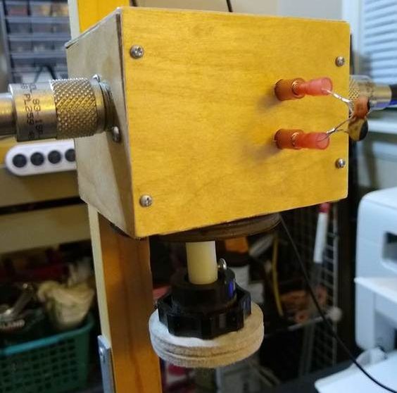
The simplest one was the knob. Tossing around among my junk my eye caught a pack of self-sticking felt furniture pads to protect a hardwood floor from being scratched by moving furniture. I stuck two 2-inch ones together then stuck the pair on the face of the smaller knob I was already using. Works very nicely! It even feels good. And doesn't look terrible. I put some talcum powder on sticky face that the knob doesn't cover to it doesn't even stick to your fingers!
The capacitor was a bit more involved. I wanted to use banana jacks and plugs, but didn't have any. However I did find in one of my junk drawers two pairs of plug-jack things normally used in wiring. I think they will work in the short term.
|
My second issue was that I couldn't find an appropriately sized capacitor! But by soldering a couple capacitors in parallel I came up with about 140pf which allows my variable to tune the entire 40 meter band nicely. Haven't had a QSO with it but did hear a few weak signals on the band which gives me hope! The SWR curve is much sharper than when I was using a different capacitor shown below.
|
2018-12-24 A good Christmas eve day activity seemed like it might be to measure signal strength from the loop! So I set it up in a pretty open part of the house, about 8' from the island in our kitchen. I put the field strength meter (FSM) on the island and my x5105 on the corner of the dining room table next to the antenna which was on my camera tripod. Then I hay-wired my CW key so it would stay closed, reduced the power to a half watt and transmitted away, first on 30 meters, then on 20 meters and finally on 17 meters. Results were quite similar on all three bands so I didn't go further. Now think of the right side of the loop (looking at the photo below) on a clock dial as 12 o'clock, and the left side as 6 o'clock and you'll perhaps understand what I'm trying to explain!
On 30 meters, with the 12 o'clock edge pointed at the FSM it read 435mv. With the 3 o'clock edge toward the FSM it read 164mv. With the 6 o'clock broadside toward the FSM it read 387mv and with the 9 o'clock broadside toward the FSM it read 190mv. So Its front and back signal strengths are approximately the same which are about twice as strong as the broadside readings. The numbers on 20 meters were similar in direction but the front signal was about ten times as strong as the broadside. The 17 meter comparison was the same in terms of direction but the ratio of front to side was about 3 to 1. So the antenna is clearly directional, at eight feet anyway!
|
2018-12-23 After just a few relatively minor changes to the antenna this afternoon, none of them having to do with it's performance but rather its ruggedness and appearance I tuned around on the the 30 meter band and heard W5ZR at 10.119mhz in QSO with a station in Michigan. His signal was an almost steady 579 so I peaked the antenna at that frequency to a 1:1 SWR. Then I rotated the antenna to find the peak at 599.
When he finished I gave him a call using 5 watts with my X5105. He came back and gave me a 579 with some QSB. We had a ten minute or so QSO, he running 200 watts to 2 element quad, so he gets some of the credit!
|
Note: the center conductor and shield are soldered together at both ends of both the main loop and the small drive loop.
|
But no matter, the loop antenna works. That makes three QSOs with it, the other two on 20 meters while it was still in a rather makeshift condition. It's nice to know that it works on 30 meters, which is below its "optimum" given the loop circumference of 109 inches including the capacitor. Oh, by the way, the antenna, as pictured above just after the QSO, was only about four feet off the floor of my ground floor ham shack/office! Thanks, Bert for the QSO.
I have to say that I was surprised by the contact today. In spite of the testimony of others, I really have had rather low expectations for this thing. I tackled the project more to understand small loops than to actually use. I'm sure it is not "the best" antenna one can use but it has proven to me that it really is a useful one. To minimize hand capacitance I attached a short plastic shaft extension with a plastic knob. That appears to have completely solved that problem. and the rate of tuning is not too difficult to deal with.
2018-12-22a Another day spent on this crazy antenna. I decided to replace the capacitor with a two stage one that has nearly the same tuning range but there are no movable connections in the RF current path of the main loop. That's because one end of the main loop goes to one of the two sets of fixed plates and the other end of the main loop goes to the other set of fixed plates. The rotating plates which are connected to the shaft have the effect of connecting the two fixed plate sets in series electrically. But the signal never goes through any moving contact or wiper. The capacitor is from an old AM radio that I scrapped some years ago and has fairly wide plate separation. Further since the two variable capacitors are in series, the voltage is divided between them, albeit not evenly since the two sets of plates are of different capacitance values. The capacitor also has a large pulley which makes tuning it simpler. And there is less hand capacitance effect. I'm contemplating rigging up a dial cord arrangement which would make tuning even easier and totally eliminate hand capacitance. We'll see.
Once everything was assembled I checked the SWR. With this capacitor it tunes 30, 40, 20, 17, 12 and 10 meters! As the graphs below show the SWR curves look quite good with a near 1:1 SWR on all bands. No on-air checks since by the time I finished building it, those bands had gone to bed! Maybe in the next couple days I can do some on-air tests, hopefully a QSO or two!
2018-12-22 Overnight I got to thinking about my transformer concept. It struck me that the number of turns of both the "primary" and "secondary" are the same, one turn. That seems more like an isolation transformer than a matching transformer. With a normal transformer if you have the same turns on both the primary and secondary you have very close to the same voltage and current in both! Double the number of turns on the secondary and you have approximately double the voltage on the secondary as primary, etc. But in this case, the only difference is the circumference (or diameter) of the two winding's, and the consequent difference in inductance. How does that "transform" the impedance? After doing quite a bit of reading no one else seems to address this so I'll quit worrying about it!
But I did decide to experiment with small loop circumference using my original single #12 wire loop. My 20 meter data:
- 14" loop, ~75 ohms, 1.0 SWR.
- 17" loop, ~50 ohms, 1.0 SWR. 22" loop, <50 ohms, 1.1 SWR.
- 30" loop, ~11 ohms, 1.5 SWR.
I then decided to do some more careful measuring with my RG8x driving loop. It seems to follow those same behaviors. Overall, I conclude that driving loop dimensions are not super critical. So go with the general guideline of about 1/5th the circumference of the main loop and use whatever material you have available.
After reading the AA5TB article above I have decided to try a different capacitor. He makes the strong point that resistances in the main loop must be kept to an absolute minimum. One of the main sources of resistance are the contacts in a variable capacitor. His suggestion is to use either a butterfly capacitor or just the stater sections of a multi stage capacitor such as used in older broadcast radios. That removes any moveable physical connections from the circuit as the rotor in the latter case simply acts as a series bridge between the two stater's with only capacitance coupling. I know the rotor connection in the current capacitor is very fragile and minimal, unable to handle much current. I've got one that has an almost identical tuning range when used as he suggests, so back to the work bench!
|
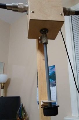
2018-12-21 There are many good YouTube videos on building Mag Loop antennas and I've gotten considerable help from some of them. The one I watched last night (I don't recall which one that was) had an idea the I knew immediately that I needed. One of the problems with the capacitor is the effect of hand capacitance. If you just move your hand near it, the resonance point will change. At least one person rigged up a motor driven capacitor with remote control. Clearly a solution but also a significant complication. The one that caught my attention was a guy who used a several inch plastic extension on the shaft so his had was kept well away from the capacitor when tuning. Today along with a few other changes to dress the thing up a bit I incorporated that. The picture at right shows how I did it. And it works very well!
I didn't have time to actually work anyone today on 20 meters but I heard and tuned several stations. With that extension I was able to tune to lowest SWR quite easily after initially tuning for peak noise.
|
2018-12-20 Two or 1-1/2 QSOs is hardly solid data to analyze an antenna, but it is exciting, especially when it is with an antenna the likes of which you have never even played with previously in your career. And that is the case with this magnetic loop. To me they always seemed like a joke. But now I am convinced they are a serious antenna. The first qso with NM1I in MA, 800 miles east was on December 18 at 1650z on 14.033. He was initially a solid 559 but faded to unreadable but not before I had gotten everything. He gave me a 339 but I don't think he got my second transmission at all, hence the 1/2 QSO! The second was yesterday at 2037z on 14.057 with W5MIG in Texas, 1000 miles. He gave me a 449 and he was a solid 549 in here. Both were made using my x5105 at 5 watts. That one was interesting because I had just had a QSO with him at 2027z, also with the x5105 at 5 watts but using my G5RV station antenna.
He was 579 in here and gave me a 539 using my G5RV. He didn't know I was going to call again as the thought just hit me when we finished. I have to say I was surprised that he heard me and responded. Thanks to both Butch and Jerry for "making my day!" Both times I had my loop sitting on a bar stool upstairs in our home where I could rotate it easily. I heard W5MIG with the antenna down stairs but very weekly. Those two contacts convinced me this is a viable antenna so I'll be making "improvements" to it and once the weather warms will be playing with it outdoors.
|
2018-12-19 I think I am closing in on a "final" version of my mag loop! Famous last words. An antenna is never "done!" But this one is about as good as I can make it in its present form. And I'm fairly pleased. I have now had 1-1/2 QSOs with it, both on 20 meters. Both CW. both from our upstairs bedroom! Location wise, I know that is not a permanent location! But the ten or twelve feet higher with open space to rotate it makes a difference, I think.
So here are the specs.
|
|
- Small loop: 21" in circumference (about 8" diameter). RG-8x with the center conductor and shield soldered together at both ends so it will behave like a single of wire approximately 1/4 inch in diameter. Connects to a BNC jack (for the feedline), one end to the center the other end to the outer or ground side of the jack. The small loop measures about 0.6uh.
- Capacitor: Junk box variable with fairly wide plate spacing adjusts from 10pf to 101pf. Resonates the loop on 30, 20 and 17 meters. I may add a way to plug a fixed capacitor externally to allow resonating on 40 meters.
- Capacitor Box: I built the capacitor box from 1/16th inch hobby plywood assembled using balsa corner blocks, cemented together with Insta-Cure CA from HobbyTown.
- Feedline: Four foot piece of RG-174 terminated both ends with a BNC connector.
Observations:
- It is quite directional with strongest signal in the plane of the loop and fairly deep nulls broadside to the loop.
- SWR is very low at resonance, no tuner is required.
- It can be tuned up on 40 meters as well as 15 meters but the calculator above indicates it will be low efficiency 40 meters.
- Bandwidth is very narrow as the Q is very high which makes tuning tricky. Furthermore hand capacitance is an issue. A larger knob might help with both.
- Most importantly, it does actually work! In good band conditions I can imagine it would work very well. And it was fun to build. Building it took magnetic loops from mystery to reality for me. Like all antennas, it is very simple in both concept and physically. I'm guessing it is not by any means the world's best antenna, but it is clearly an option and one that will work indoors or where antenna supports are a problem.
2018-12-18a After the "success" mentioned below, I found a light weight, ten foot piece of 1/2 inch copper pipe in the garage. It had been under the house in the crawl space for some reason and the builder pulled it out. Suddenly, I have the main ingredient to make a more robust loop. Not sure it will be as portable as I was originally imagining, but it will certainly be overall "better", depending on my building skills! The calculator above says to make it into an octagon I need 8 sections, 1.25 feet each. My first thought was to buy 45 degree elbows but now I'm thinking I can make eight 45 degree bends and avoid needing the elbows and all the soldering involved. We'll see. That will be tomorrow's project. I've got a number of capacitor combinations I can use and I'll start with the small loop I already have although with a ten foot circumference for the main loop it should be 24" rather than 21". Will be interesting to see how big a difference that makes.
|
2018-12-18 I started today by making a new small loop using 21" of RG-8x, soldering the shield and center conductor together to form a single conductor that is 1/4 diameter. An alternative would have been to use 1/4 copper tubing or something similar. One end of this driving loop is soldered to the shield side of the BNC connector and the other end to the center conductor, forming a single turn loop about 8" in diameter. the feedline connects to the BNC connector.
|
|
I just hung the loop on the fastener for the shock cord which was holding the top of my main loop up as shown below. The capacitor is a 14-310pf variable. Once connected I used my x5105 SWR scan function to run a bandwidth scan on 40, 30, 20 and 17 meters which are shown below. It may just be me but it seemed that tuning was much more critical with these larger diameter wire loops than previously. Perhaps that reflects less resistance in the elements so less energy is going to heat and more to radiation?
I noticed a difference immediately when I tuned 40 meters. I heard actual ham SSB transmissions. My "lab" is on the ground floor of the house so I decided to go upstairs to our main bedroom which has a large open space at the foot of the bed. My wife is out shopping right now so please, don't tell her! I again noticed a difference on 40 and tried but couldn't raise anyone. The Mag Loop Calculator above indicates that its efficiency on 40 is very low, about 5% or so I think. But I did notice that it is pretty directional. By rotating it on the bar stool I could see and hear quite a difference in signal strength. I also noticed a distinct noise on the band when "pointing" toward the neighbor's house which almost completely faded when I turned it broadside toward the house. So as indicated in some of the articles I've read it effectively blocks unwanted noise (if the signal you want is about 90 degrees from the noise source.
Just to check to see if there was any activity on 20 meters I tuned up there and almost immediately heard NM1I calling CQ from MA on 14.033. So I tuned the capacitor for that frequency and went back to him. I was so nervous that it took me a while to discover my power was at 0.5 watts and then get everything tuned. But then I gave him a call and to my amazement he came back! Thanks Butch. He gave me a 559 and he was about 339 here but we lost contact as his signal began to fade during his initial transmission, dropping out completely. I never heard him again. But that was enough to light my fire! I'm sure this will not be my final rendition of a small magnetic loop antenna! They actually do work! And I can't say enough about the xiegu x5105 transceiver, especially its SWR sweep function which makes building and tuning antennas a breeze, well almost! Seriously, it does work very well and it's nice to be able to punch the button, see exactly where your antenna is resonant, its SWR at resonance, tweak if necessary and then immediately transmit. No cables to change or anything. Pretty slick.
Another observation is that the signal a few feet from the loop is about twice as strong to the right as it is to the left. and it is even lower broadside to the loop. I've read as much in other places but it is interesting to actually observe it. I used my DIY field strength meter to make the measurements.
2018-12-17 I decided to redo the loop using some Low loss RG-8 coax I purchased years ago from Davis RF, their Bury-Flex Low Loss coax, to use with a 900 mhz FM rig. It is 0.4 in od. The piece I have is 8ft, 9in (106") long with PL259 connectors on each end. I rigged it up with the same capacitor I used below, 16-210pf. The small loop is 10 inches in circumference. I tied the center conductor and shield of the new loop together at both ends to form a single-like conductor. At near full capacitance it shows an SWR of 1.1:1 on 40 meters. on 30 meters it is 1.0:1. 1.6:1 on 20 meters and 2.2:1 on 17 meters.
The article above states that the circumference of the small loop should be about 1/5th the circumference of the main loop which is about 21inches in my case. I tried making the small loop from 75ohm cable TV coax but to my surprise the shield is made of aluminum foil and wire which doesn't solder well!
The question I am contemplating is why the SWR goes up with frequency?
2018-12-10 As I've thought about the magnetic loop antenna it strikes me that it is simply a tuned-secondary RF transformer with an un-tuned primary. The one turn (usually) secondary is high impedance and couples to the "ether" while the one turn primary is roughly 50 ohms and couples to the transmitter. That is similar to the tuned-secondary matching transformer circuit I used with my end fed half wave antenna with the primary difference being that a "radiating element" was attached to the secondary in the case of the end fed half wave whereas no such radiating element is used with the magnetic loop. I guess the secondary itself IS the radiating element.
If that is even close to a valid way to think about it that also helps explain why the conductor size and RF resistance of the secondary is such a big deal as it is in essence in parallel with the impedance of the ether as seen by the secondary. And in a parallel circuit the lowest value is the dominant one and will be the biggest factor in absorbing energy.
For whatever reason around 36 inches seems to be a practical trade-off diameter for the secondary turn in many of the examples I've looked at. So I dug around in my junk box and found an almost perfect length of low loss 3/8 inch coax. When formed into a circle its inductance measures 2uh. My junk box also yielded a 16-210pf variable capacitor with fairly wide spacing between the plates. So my plan is to start my project with those. I haven't decided on what I'll use for the primary yet but am thinking of a piece of old cable TV 75 ohm coax. the references I found indicate it should be 1/5th the circumference of the secondary which is about 20". I'm planning this for use with a QRP transmitter, 5 watts.
|
2018-12-10a After getting most of my chores for the day done I decided to "build" the main loop. I say build with tongue in cheek as I really kind of hung it together. I wanted to see if it really would resonate near some useful frequency using the 16-210pf variable capacitor.
Rather than using the piece of coax mentioned above I tied all three wires of a 102 inch piece of 12AWG with ground electrical wire together. Then I "hung" the wire on a 40 inch piece of wood attached to a piece of OSB flooring and soldered the ends to the capacitor.
|
Loop, counter dipper and capacitor setup on left. Center shows the connection to the capacitor. Right shows the home brew dipper.
|
Finally, using my trusty home brew FET dip meter set to about 14.05 mhz as indicated on my antique frequency counter I tuned the capacitor to see if I could find a dip. I DID! In fact I could tune it all the way from 18mhz down to 6.7mhz. Not sure that is a practical range for use but it does resonate over that range. My experiment is successful! All I need to do now is add a small loop and see if I can get a useful match to a transmitter!
2018-12-10b Well, I quick threw together a loop made of 20 inches of #12 electrical wire and soldered the ends to a BNC connector. Then using tie wraps I attached it alongside the top of the large loop. A quick check indicated that the main loop resonant frequency wasn't affected much so I tuned it to 14.05mhz. Then using a three foot piece of RG-174 coax terminated with BNC connected the small loop to my Xiegu X5105 and ran a SWR scan with it. To my amazement and pleasure the SWR looked just like it should with the lowest point near 1:1 at roughly 14.05mhz! I ran SWR scans for 30 and 40 meters as well and the plots for all of them are below. The concept is proven!
Would it, will it work on the air? I guess that comes next. Then I may build a "nice one" properly! Though I am very pleased with this concept model.
