40/20 Meter Trap-Inverted Vee
In nutshell, a trap dipole or inverted vee is like a link dipole or inverted vee only instead of using alligator clips to connect/disconnect the various segments for each band a parallel resonant trap is used. You start with a dipole/inverted vee cut to length for the highest frequency band you wish to use, in my case 20 meters. Once that is trimmed you connect a parallel resonant "trap", which is tuned to the center frequency of the just -completed segment, to the end of the segment. The principal is that at resonance a parallel resonant circuit has a very high impedance across it so it looks pretty much like an open circuit to the antenna. If you were making a linked dipole/inverted vee, you'd place an insulator at that point. Then you add a length of wire to the open end of each trap so that the combined length is now cut for the next lower frequency, in my case 40 meters. At that point you would attach the end insulator and your done.
Well, your not quite done! In a perfect world (which is essentially the case with a link approach) the trap would completely isolate the lower frequency extension from the original higher frequency segment and you would be done. But in the real world traps have a very high impedance but not quite infinity which means the 40 meter extension, in my case, is not completely isolated and exerts some influence over the 20 meter segment. In my case, comparing it to my linked inverted vee which has links for 20, 30 and 40 meters, the 20 meter segment of this trap inverted vee is 3-1/2 inches shorter than the same segment of the linked inverted vee. To deal with that you take a trial and error approach to find the balance between the length of the two segments. Hopefully you wrote down the "exact" resonant frequency of the 20 meter segment prior to attaching the trap and 40 meter extension so you can now see the impact of the 40 meter extension on the 20 meter segment and increase or decrease the length of the 20 meter one accordingly. Keep in mind that this will shorten or lengthen the 40 meter overall length so you may need to make adjustments to it accordingly. hopefully it will only take a few minor trims or additions to get it right.
One final thought. due to the influence of the two segments of the antenna on each other the resulting useful bandwidth, generally considered as the 2:1 SWR bandwidth, will be noticeably less than with a stand along dipole or even the link dipole. So you may want to pay a bit more attention to the frequencies in each band you primarily use. With a tuner or forgiving rig you can use the whole band but the SWR may rise to 3:1 or greater at the extremes. But it's worth the trade-offs. The result is a very good, convenient, multi-band dipole/inverted which will give you excellent operating results. It would probably be difficult to prove any real world performance difference between this antenna and a stand alone dipole/inverted vee or the linked version. The primary issue is convenience of use and the novelty of using traps!
2018-10-18 This afternoon, before replacing this antenna to give my lonely 35 ft end fed one some attention, I had a couple QSOs on 40 and 20. The most exciting one was on 14.061 with WB5USB, a SOTA activator in New Mexico on Ortiz Mountain, 1110 miles southwest! I'm not sure what he was using though his QRZ page would suggest it was a KX-3 and vertical or end fed antenna. I was using the x5105 and this antenna. Copy was fairly rough on both ends but we got the details across! He gave me a 229 and I gave him a 449. I continue to be impressed with the simplicity and effectiveness of this antenna. I've ordered a couple more pairs of traps and plan to trap it for 30 and 17 meters as well, thereby having a resonant antenna on 40, 30, 20 and 17 meters. There is some real beauty to not needing a tuner, even when your rig includes one.
2018-10-17 One of the problems with having a bunch of portable antennas is that you need to keep the cobwebs off them. You don't want them to become lonely and jealous. So after spending several days with my 17 ft vertical and 35 ft helical wound vertical, I decided to put up the 40/20 trap inverted vee. Both verticals gave me some good contacts and clearly are usable but I think they are truly compromise antennas and would, under normal conditions, not be my antenna of choice. having said that, the simplicity of the 17 foot wire one in particular makes it a great option if one is in a hurry and or in a very limited space. But verticals are noisy and just tend to think resonant dipoles are overall better when an option.
I used two 25 ft BNC terminated RG174 coax lengths joined with a female BNC coupler to connect the antenna to my radio. Tuning around both 40 and 20 meters things were pretty quiet. I decided to tune to 14.060, the 20 meter QRP calling frequency, and have a try. Before I could hit the key, WU5M called CQ! He was reasonably strong, and guessing he was also QRP, I went back to him. He was about a 549 in here in Wisconsin and gave me a 579 in Texas. He was running a KX3 at 5w and a hexbeam antenna on a push up pole. I was using my x5105 at 5w and the trap inverted vee I had just put up on my Shakespeare TSP20 Six-Piece Wonderpole. We had an old fashioned Rag Chew that lasted 20 minutes, solid copy all the way! QRP and home brew antennas are fun!
2018-09-22 I recently ordered some antenna wire from Sotabeams. At 0.04 in diameter, it is 0.01 in larger than the Silky 26GA antenna wire from The Wireman Inc. I had taken apart one leg of my trap 40/20 inverted vee to use elsewhere but when this Sotabeams wire arrived yesterday I decided to rebuild that leg of the trap antenna using the new wire. Of course one needs to check it out to see if it works as hoped. So today I strung it up using my Shakespeare TSP20 Six-Piece Wonderpole mast.
Initial checks indicated that it worked on both 40 and 20 so I gave it a try with my X5105 and made two CW contacts within about half an hour, one with a station about 600 miles away in Alabama and the other 550 miles away in Missouri. Solid copy both ways with both. There was no activity on 20 meters so couldn't test that on the air. Then I used the SWR sweep feature of the X5105 to look at the SWR curves on both bands. They are shown below. I'm pretty happy with the antenna.
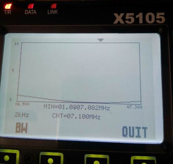
Trap inverted Vee 40 meter SWR curve as plotted on the X5105.
|
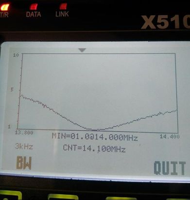
Trap inverted Vee 20 meter SWR curve as plotted on the X5105.
|
2018-08-10 This afternoon I decided to try the 40/20 meter trap inverted vee with my 5.4 meter Bamboo Pattern 11 Section Telescoping Fishing Rod and see if I could make some contacts. As expected the FT817nd liked the low swr on both bands and put out full power on both 40 and 20. There were very few QSOs on either band but I did finally snag one 40 meter CW QSO with KC0M in Branson, MO, just under 400 miles away for a brief but solid QSO. He gave me a 579 and he was a strong 589 in here. The antenna set up easily using the shock cord arrangement described and shown below. I think it is a keeper. For more about the setup click here.
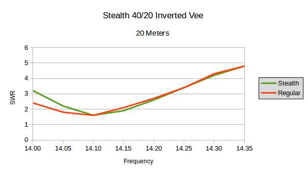
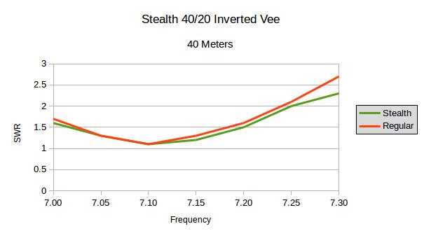
2018-07-23 Today I trimmed both the 20 meter and 40 meter elements of the inverted vee to get them where I wanted them. Each leg measures 30 ft, 3 in from from center insulator to tip. The trap is located 15 ft, 6-1/2 in from the center insulator. The SWR curves are below plotted along with the speaker wire version I used for field day. I'm guessing the differences are due to installation and measurements, neither of which would be identical though very close.
Rebuilt Trap inverted vee using Silky 26GA antenna wire.
|
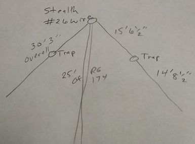
Final measurements of Stealth 40/20 meter inverted vee made with Silky 26GA antenna wire from The Wireman Inc.
|
2018-07-21 I guess it's obvious that once I get on a kick I can't leave well enough alone. So I decided to remake my 40/20 meter trap inverted vee using some new wire I ordered from The Wireman Inc. . It is their Silky 26GA antenna wire, part number 534. It is extremely light, fairly strong and jet black, making it more stealthy than the speaker wire. The finished product weighs 3.3 oz., less than my 35 foot end fed antenna with the same wire! The difference is that this one doesn't need the 9:1 unun. I'll do some trimming and insert the SWR curves.
I was able to check into MidCars around noon CDT on 7.258 SSB and talked with Dan, WB8EEW about 300 miles east in Fairfield, Ohio. He was S8 in here and gave me an S5 with QSB. Not bad for 5 watts in today's conditions.
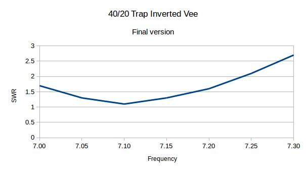
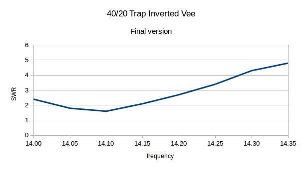
2018-06-07 After one more tweak of the antenna I think I've done my final version and test prior to using it for field day. The graphs below show the results. Both bands are tuned toward the bottom of the two bands as I work mostly CW. The SWR on both bands near the resonant frequency is very near 1:1. And it is usable across nearly the entire range of both bands. Conditions were not good this afternoon on either band but I did manage one QSO with a station just over 700 miles east on 20 meters. He was a 589 in here and gave me a 449. We completed the ten minute QSO successfully.
Summary of Final Antenna
|
Leg lengths: 29 ft, 9 in. from center Insulator to tip of each leg. The trap is 15 ft, 5 in. from the center insulator. Resonant frequency with tip of leg about 5 ft. above ground: 14.1 mhz (SWR 1.6:1) and 7.1 mhz (SWR 1.1:1). Elements made with RCA #16 Speaker Wire. Traps are SOTABEAMS Pico Traps. Mast is a Shakespeare TSP20 Six-Piece Wonderpole fishing pole with the top element removed so the antenna center is 16 ft. 6 in. from the ground. Measurements were made using a MFJ-259B HF/VHF SWR Analyzer.
|
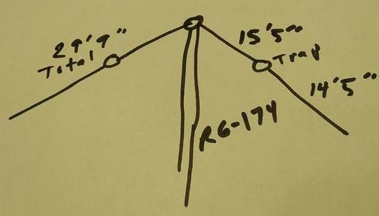
Measurements for the portable trapped 40/20 meter inverted vee.
|
|
|
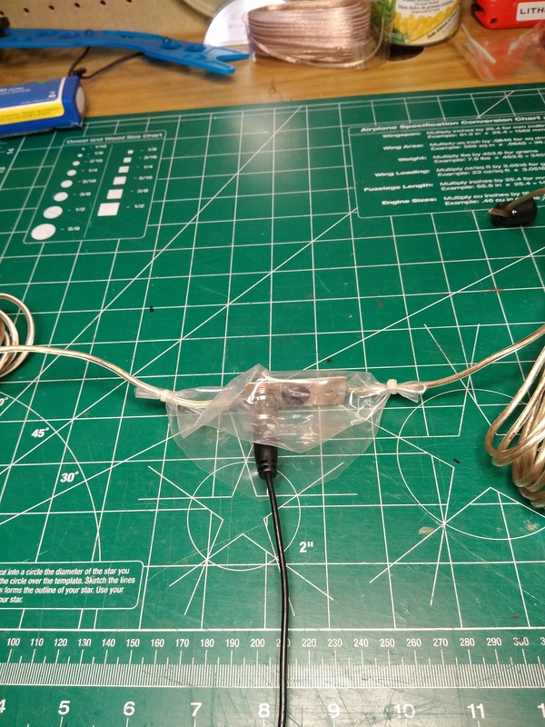
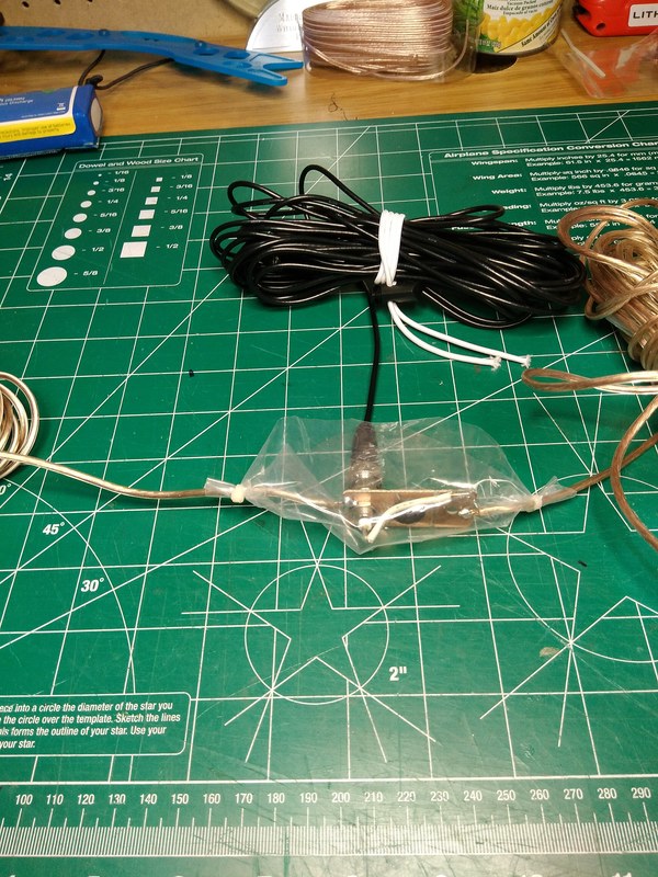
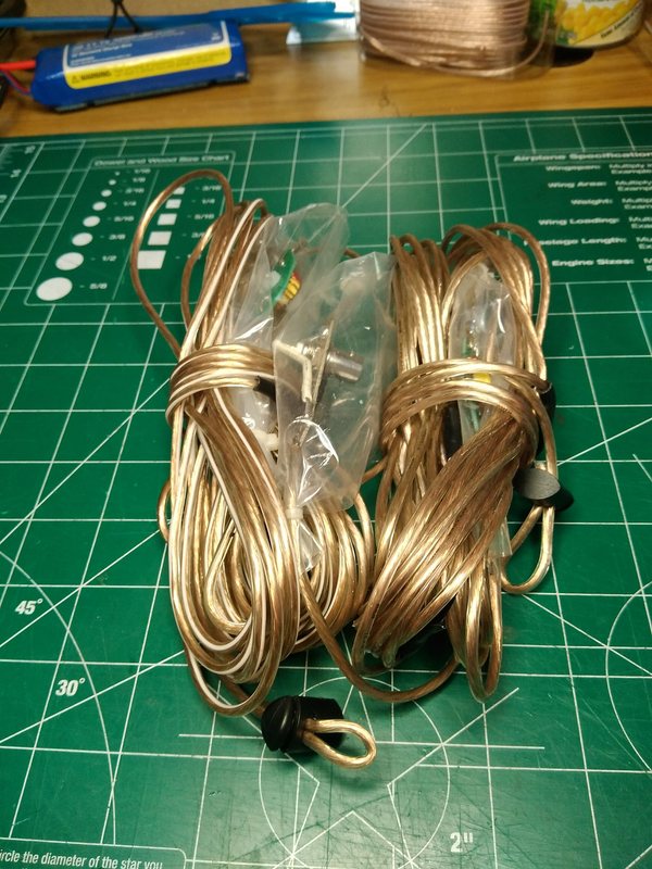
The pictures below show how I water proofed the center insulator and the traps using some pieces of sheet plastic and tie wraps. The final picture shows the antenna all wrapped up for transport.


2018-06-05a After dinner I decided to give the trap inverted vee one more try using Richard's suggestion. So I attached a roughly sixteen foot piece of wire for each 20 meter leg to the center connector. without traps attached I tied off the ends with shock cord to tent stakes and measured the frequency. It's resonant frequency was 14.82mhz. Then I added the traps and 40 meter extensions (about 13-1/2 ft) and checked it again. The resonant frequency had dropped to 13.11mhz. I trimmed about 2 inches off the 20 meter legs and the frequency increased to 14.14mhz.
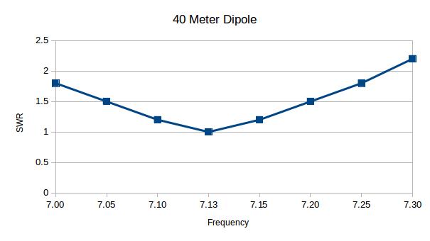
The 40 meter resonant frequency was 7.35mhz. So I added 12 inches to the 40 meter extensions the the 20 meter resonant frequency did not change noticeably. But the 40 meter resonant frequency decreased to 7.17mhz. I did the charts below at this point. I included the chart for a 40 meter inverted vee for comparison.
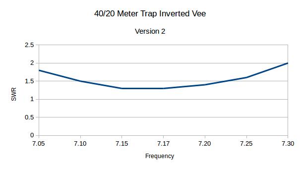

The leg lengths for the antenna above were 15 ft, 2 inches from the center connector to the traps and each leg was 29 ft, 9 inches from center connector to the end of the 40 meter leg extension. So the 40 meter extension from the trap to the end was 14 ft, 7 inches. The SWR at the top end of 20 meters is high but pretty much what is expected.
2018-06-05 As mentioned on my page comparing the trap and fan style antennas, the SWR of the trap antenna on 20 meters seems higher than I expected, particularly at the top end of the band. So I emailed Sotabeams to see if I could get some ideas to try to solve that. Richard G3CWI ([email protected]) wrote back almost immediately, stating, "You would need to adjust the 20m section first then do the 40m one. Trapped dipoles are quite fiddly to get right." So I plan to give it another go and see what happens.
In the meantime I have concluded that the #24 RCA speaker wire is just too fragile for a practical antenna. So I plan to go back to the #16 or #18 wire for continuing experiments.
|
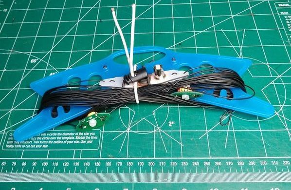
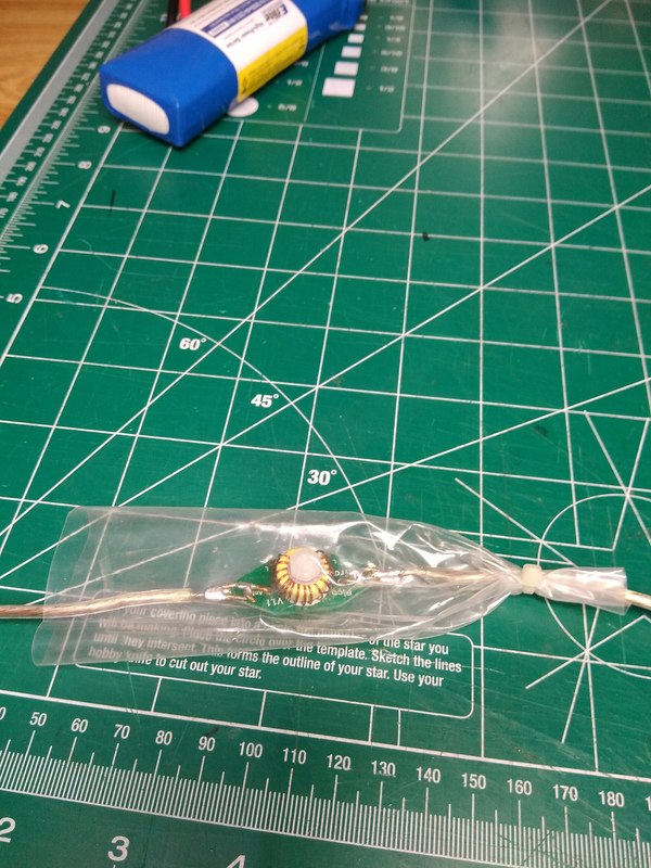
2018-06-02 After playing with the trap style inverted vee for a few days I decided to see if I can make it even more portable by using smaller speaker wire. The result is pictured at right. Using #24 wire and the dimensions of the previous one it weighs in at 2.7oz (vs. about 8 oz) and forms a very small bundle. Will test it out soon and post the results.
|
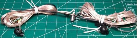
40/20 meter trap inverted vee made with RCA #24 speaker wire.
|
2018-05-24 Today I borrowed a MFJ-259B HF/VHF SWR Analyzer from my neighbor Jerry, N9AC and hung my antenna again. The lowest SWR Frequency on 20 meters was 14.032 (1.5 SWR) with the 3.0 SWR bandwidth being 13.963 to14.156. On 40 meters it was 7.215 (1.2 SWR) with the 3.0 SWR bandwidth of 6.925 to 7.44 . After some tweaking, the center frequency on 20 meters is 14.028 and on 40 meters is 7.224. My final dimensions are Center insulator to trap, 15'7". Trap to end 13'9". Overall leg length, 29'6" (one inch for the length of the trap.)
I then set up my Fan type Inverted Vee. It's center frequencies are 14.107 (1.1 SWR) with the 3.0 SWR bandwidth of 13.8mhz to 14.454mhz) and 7.07 (1.3 SWR) with the 3.0 SWR bandwidth of 6.75mhz to 7.35mhz).
My initial response is that the fan approach is superior, providing both a lower resonant SWR and broader useful bandwidth. I had a QSO with both antennas with W5FOC. He gave me a 599 on the fan antenna at about 2:45 on 20 meters and a 579 on the trapped antenna about 45 minutes later, also on 20 meters. I felt like the noise floor was a bit higher on the trapped antenna too but that is very subjective.
|
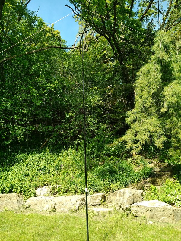
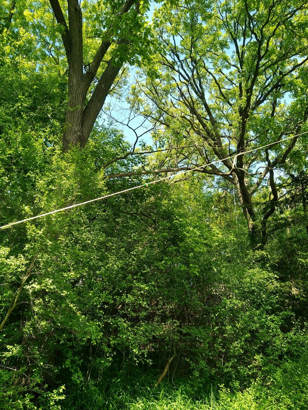
2018-05-23 So, this afternoon I took my FT-817, MFJ Model MFJ-204B Antenna Bridge, Shakespeare TSP20 Six-Piece Wonderpole and trapped antenna out to the back yard and set it up. The mast is 16' 6' tall. An initial check once all was setup showed the resonant frequencies were 13.85mhz and 6.78mhz. After running around like a chicken with its head cut off I finally arrived at 14.070mhz and 7.220 mhz.
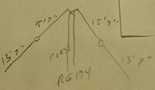
The lengths were as shown on the sketch: 15'7" to the trap and 13'7" to the end of each leg. That is a total leg length of 30' 9". The center of the antenna was 16'5" above ground and the ends drooped down to about three feet.
|
|
|
|
The pictures don't do a very good job of showing the antenna but they are an attempt. What they do show is that the trees in my back yard have really leafed out since I began playing with my fan inverted Vee just twenty days ago!
It was interesting to observe that the length of the 40 meter segment had very little impact over the resonant frequency of the 20 meter segment. But, as expected changing the length of the 20 meter portion did impact the 40 meter
|
frequency. The impedance on both bands was 75 ohms according to my MFJ Antenna Bridge. Once I got it close using my MFJ Antenna Bridge I switched to my FT-817nd. On 40 meters, using the lengths shown above the FT-817 showed no SWR and put out full power from 7.005 to about 7.150. Above that is showed a couple bars of SWR and reduced its power output by one bar. On 20 meters it showed three bars of SWR from 14.050 to about 14.1 above which the number of bars went up. Its output power was reduced by one bar above 14.1. It's unclear what that means. I think I'll borrow my friends Antenna Analyzer and look at the antenna some more.
The bands didn't seem to be very good today. I heard W1AW's code practice and just a couple other stations but wasn't able to make any contacts. Was that the antenna? Who knows! But I don't think so. More to come, but I am pleased with everything except spending the whole afternoon running from one leg of the antenna to the other to trim the wire, then to the rig to look at the results.... You get the idea!
2018-05-22 OK, I got a bit more done today. I fabricated my center insulator, very similar to the one I made for my fan inverted vee. Then I got some speaker wire, heavier than I really need and cut it into calculated lengths for the 20 and 40 meter sections. I cut the 20 meter ones at 16' 9", just a bit longer than the formula suggested and very close to the lengths shown on the SOTABEAMS Pico Trap page. I cut the extension after the trap to 14' 6", referring to those same calculations.

|
Top and bottom sides of the center insulator.
|
Top and bottom side of one of the traps.
|
One concern I had was how to attach the antenna elements to the ends of the traps. The holes are very small and don't look all that rugged. I ended up fabricating a loop from #16 solid coper wire that I think will take the strain and can be soldered and unsoldered many times while I attempt to tune the antenna. I really don't have any idea how difficult the tuning process will be and at this point am uncertain how to go about it. I guess I'll start by getting the 20 meter legs trimmed fairly close them mess with the 40 meter ones. Should be an adventure!
|
2018-05-21 After building and playing with my 40/20 meter fan inverted Vee and with a month remaining until ARRL's Field day which inspired these efforts, I decided to try building a Trap Inverted Vee for 40 and 20 meters. As with the fan based antenna I've messed with trapped antennas previously, building a trapped end fed version using a home brew coaxial trap. But this time I chose to use Pico Traps from SOTABEAMS in the UK. I don't recall how I came across them but they are tiny and cute and looked like an interesting way to play with the idea of a trap Inverted Vee.
So this morning I opened the little plastic bag containing the several parts and built the two 20 meter traps.
|
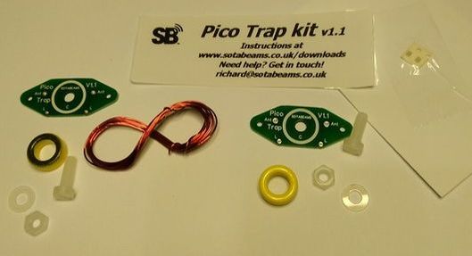
20 meter Pico Trap kit from Sotabeams.
|
My biggest concern was soldering the very tiny 100pf surface mount capacitors to the circuit board. I have a temperature controlled iron but couldn't find the tiny pinpoint tip recommended for soldering surface mount parts. I also couldn't find my syringe of silver based solder that I've used in the past. And the capacitors in the packet are small, about 1.5, maybe 2 millimeters long! The instructions suggest using a large tray to keep from losing the parts. GOOD IDEA. Those little capacitors would rather fly through the air than be soldered down. Thankfully I didn't lose the first one I tried, before getting a cookie sheet as it did fly out of my tweezers more than once, as they warned!
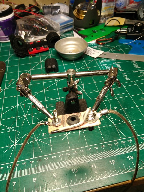
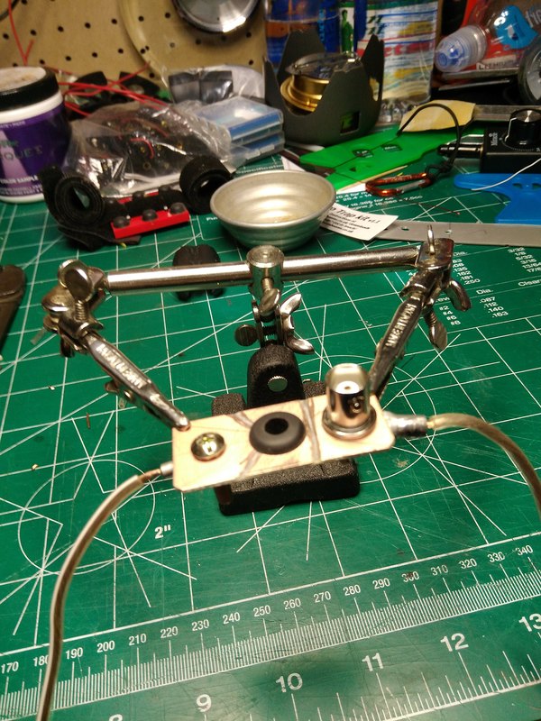
My jig to hold the tiny 100pf capacitor in place while soldering.
Then came the challenge of adjusting the resonant frequency of the traps. In an ideal world one would have nice test equipment such as the antenna analyzer pictured in the instruction sheets.
|
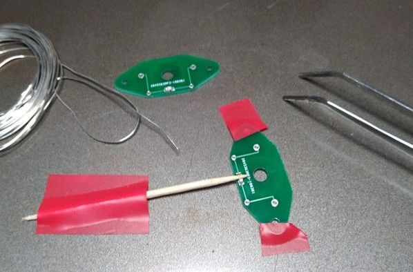
After scratching my head as to how to hold that tiny capacitor in place to solder it the idea of using electrical tape to hold the circuit board steady and then tape down a toothpick to hold the chip came to mind. It worked! What also worked was my small flat soldering iron tip and some very thin solder from my junk drawer. Success, on both traps!
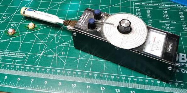
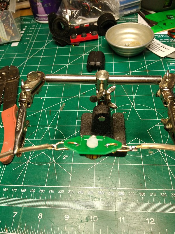
Test setup to adjust the resonant frequency of the traps.
|
Resonant Frequency of both traps (approximately!).
That completes phase 1 of my effort to build a 40/20 meter trap inverted Vee for field day. Phase 2 will be putting the wire to them. That will have to wait for tomorrow when it is not supposed to be raining as it is today. Then I can take down a previously built G5RV Jr using #16 speaker wire and re-purposing it, or at least trying to! It will be interesting to see how close it comes to the dimensions shown on SOTABEAMS web page for a trap dipole. However it turns out it has been fun so far, and that is at least half the purpose!
|
I'm kind of cheap and enjoy living in the not-so-ideal world. "Finding a way" is one of the things I like about ham radio. So I grabbed my trusty (well, it worked) home brew FET dip meter. It has a BNC connector to feed its frequency to a frequency counter. But of course, I couldn't find the power adapter that goes with my very ancient DSI 5600A frequency counter since rebuilding after a flood last year. But the idea of using my Icon IC-7000 to listen to the dip oscillator hit me. That worked!

Finished traps tuned for 20 meters.
|
In preparation for building the elements for my trapped inverted Vee I went online to search out some help. One site I found may be helpful. It is Dipole, Inverted V and Ground Plane Antenna Calculators on Hamuniverse.com. Another interesting site is An Improved Multiband Trap Dipole. I'm not endorsing either but they look interesting. I'll see if they are helpful.