17 ft. Wire Vertical for Portable Use
2019-12-20 I've been "struggling" to make a 1/4 wave vertical for 20 meters that actually is resonant on 20 meters and presents a 50 ohm load to the feedline. Seems like it should be simple but for some reason, it's not simple for me! Getting my NanoVNA has given me another way to look at the antenna. But I'm still not there. One of the displays on the NanoVNA is the Smith Chart. I recall studying it in college back in the '60s and have even used it a bit since but I think I've forgotten more than I knew!
This morning, looking at references to the Smith Chart online I came across a page online entitled, "1/4 wavelength Ground Plane Antenna Calculator." Putting 14.150 mhz in as the desired frequency it suggest the vertical element length of 16.52 ft with radial elements 18.5 feet long. His examples all focus on VHF and UHF antennas. How well does it translate to HF antennas? Good question. An equally interesting question is, "What does an antenna cut accordingly look like on the NanoVNA?" I'll be back!
Compared this antenna with the QRPGuys triband vertical that I played with more recently. That one attempts to overcome the "single band" design of this one by using switchable loading coils on the bottom rather than the balun's discussed in this article.
2018-10-15 Today, even though it was in the 30s and windy, I decided to try this 17 ft vertical with a 4:1 balun. Curiously results are similar to those with the 5:1 unun. With the 5:1 I got 1.1:1 on 20m, 1.5:1 on 30m and 1.2:1 on 40m. With the 4:1 balun I got 1.1:1 on 20m, 2:1 on 30m and 1.2:1 on 40. I was unable to land a single successful QSO today at 5 watts. Signals were pretty good but I was covered up every time I answered a CQ by bigger stations. I did get one acknowledgment from the Marine net on 14.300 but beyond my call he couldn't get anything and I couldn't get his call.
2018-10-14 Observations. Compared to my G5RV signals are one to several S units lower on the 17 ft vertical on 40 meters. That is based on a station 400 miles to the south east of me. The 35 ft counterpoise is laid out on the ground in a southeasterly direction. Two stations I tried to contact could not copy me at 5 watts but I worked them at 10 watts. That was at about 3:00pm CDT. A couple hours earlier I worked three stations in AZ and NM (around 1300 miles) on 20 meters at 5 watts. Everything was configured the same. My observation is that this is a functional antenna, not great and not awful. In a pinch and portable it would be far better than nothing.
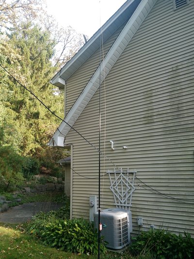
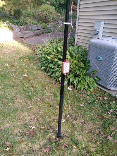
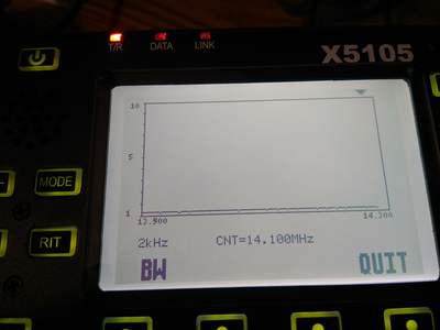
2018-10-13 The kit for the 5:1 unun came in mail yesterday so today I built it and put up my Shakespeare TSP20 Six-Piece Wonderpole in the back yard with 17 ft of #24 RCA speaker wire hung alongside the mast to the antenna jack on my 5:1 unun. I had a 35 ft piece of #18 RCA speaker wire with a banana plug on it so I used that for a counterpoise, running off kind of toward the southeast. Using my five watt Xiegu X5105 I ran an SWR sweep on 20 meters without the tuner. It showed a near 1:1 SWR across the entire band! That made me uneasy so I checked the actual SWR. Sure enough it was right. So I hastily tuned around the band and landed a QSO with K0RO 780 miles southeast in Petal, MS on 14.490! He was a solid 599 in here and gave me a 599 as well! That 17 ft vertical works!
I checked SWR on 30m and 40 m. Both are very low and it seems to hear very well and I had two QSOs with stations in Maryland and Massachusetts. SWR on 80 is 3:1 and requires a tuner. It seems to hear pretty well on 80 but I've not been able to get a QSO though I responded to a number of stations in the Pennsylvania QSO party. Not sure if that is me, "them" or both! There are lots of very strong stations on who pretty well cover up my five watts.
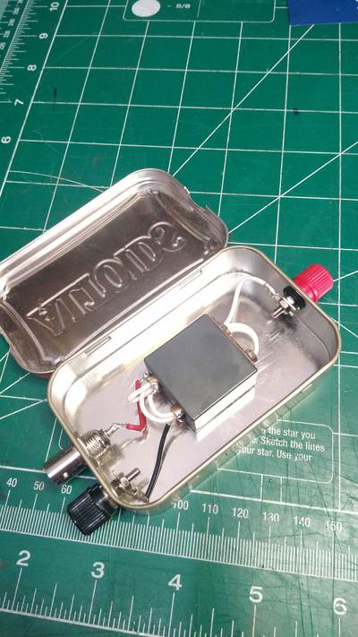
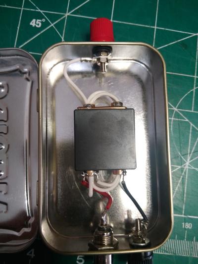
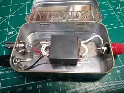
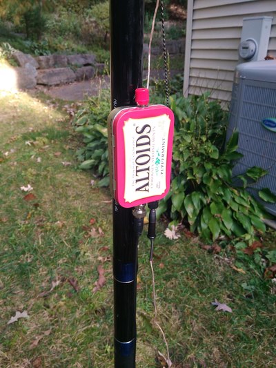
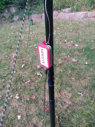
The 5:1 unun is made from the BN43-7051 kit from FairRite in France. It can be found on Ebay. Click here to see wiring directions for the 5:1 unun. I mounted it in an Altoids tin which is just about the right size and shape. I used velcro to attach it to my mast.
2018-10-01 From various sources over the past few days I got the idea of playing with a wire vertical suspended by and alongside of my Shakespeare TSP20 Six-Piece Wonderpole that I use to support my other portable antennas. I know MFJ Enterprises makes a telescopic antenna that extends to 17 feet which some portable operators like. I didn't want to sink the money into one without at least playing with something similar using what I have. Hence this effort.
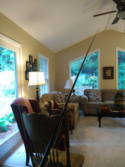
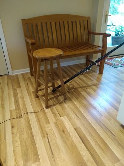
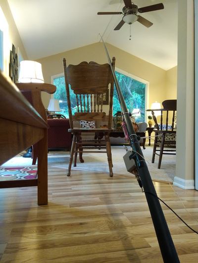
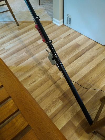
Complicating matters, we're at the beginning of some rainy, chilly days here in southeast Wisconsin which makes outdoor antenna work less fun. So I decided to at least start my experiments inside the house. Fortunately my wife is away today so if I get it all cleaned up before she gets home, all will be well! I tried two scenarios. Scenario 1) Our family room has a vaulted ceiling about twelve feet high in the center so I leaned the pole up against a dining room chair so that the tip nearly touched the highest point of the ceiling while the bottom end extended through an archway into the kitchen. That resulted in about a 30 degree angle with only the wooden chair back and the ceiling near the antenna. Scenario 2) Our stairway is designed so that the ceiling of the second floor is straight above the bottom step about 14 feet up. Be snaking the mast up in there I couldn't quite stand it up vertically but the resulting angle was about 50 degrees or so. Unfortunately it passes near a banister, the wall and the ceiling so may suffer a bit more by proximity to various materials in the walls. But interestingly, the SWR results didn't vary much between the two scenarios. I also did my tests with and without a 4:1 balun a the base of the antenna wire. AND I did some measurements with a tapped inductor from some other antenna experiments at the base. That one demonstrated that the right inductance will bring the antenna into resonance but my inductor didn't have the taps in the right place for this antenna. The MFJ one includes an inductor which is probably the best way to go.
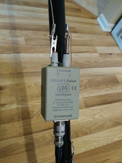
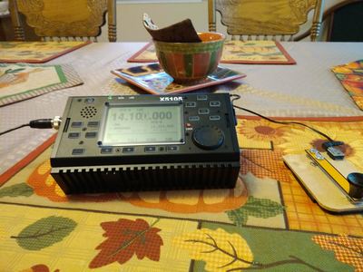
The photos above show my "test setup" such as it was. The main radiating element and the counterpoise were both made of #24 RCA speaker wire. The main element was within a couple inches 17 feet long and the counterpoise was 15 feet long. I did my tests with 25 ft of RG174 coax from the antenna to the radio, my Xiegu X5105. I used the SWR sweep feature of the X5105 to do the measurements. Special thanks to my wife for letting me use a dining chair, the dining room table and beautiful Fall patterned place-mat and the airspace in the family room. Of course, she doesn't even know about it!
Results? On both 20 and 30 meters there was little difference between the readings with and without the 4:1 balun although hand capacitance significantly changed the readings without the balun. On 40 meters the difference was dramatic, about 4:1 with the balun and near 10:1 without. Hand capacitance decreased SWR on 40 meters. On 30 meters the SWR was 3:1 with or without the balun and hand capacitance made it higher. On 20 meters the SWR reading was 1.5:1 with and without the balun and there was no change with hand capacitance.
Thoughts? Clearly the 17 ft vertical can be tuned to provide a good SWR. I should note that the X5105 internal tuner could tune it down to 1.5:1 or so on all bands from 40 through 10 meters, with or without the balun. What is not clear is how well the thing will work and the difficulty of setting it up outside as a vertical with several more counterpoises or radials, probably one or two for each band cut to roughly 1/4 wavelength. When the weather improves I'll play with it a bit more.

