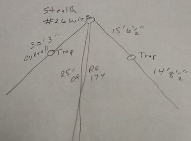
17, 20, 30, 40 Meter Trap Inverted vee
2020-03-19 On this first day of Spring I put up this four band trap antenna after playing with the 30 meter traps to get them closer together. It seems to work pretty well. Getting the traps all on the same and right frequency is no small task so I'm not sure I recommend building this antenna. At the same time if you have a tuner, either internal or external it will do the job for you.
|
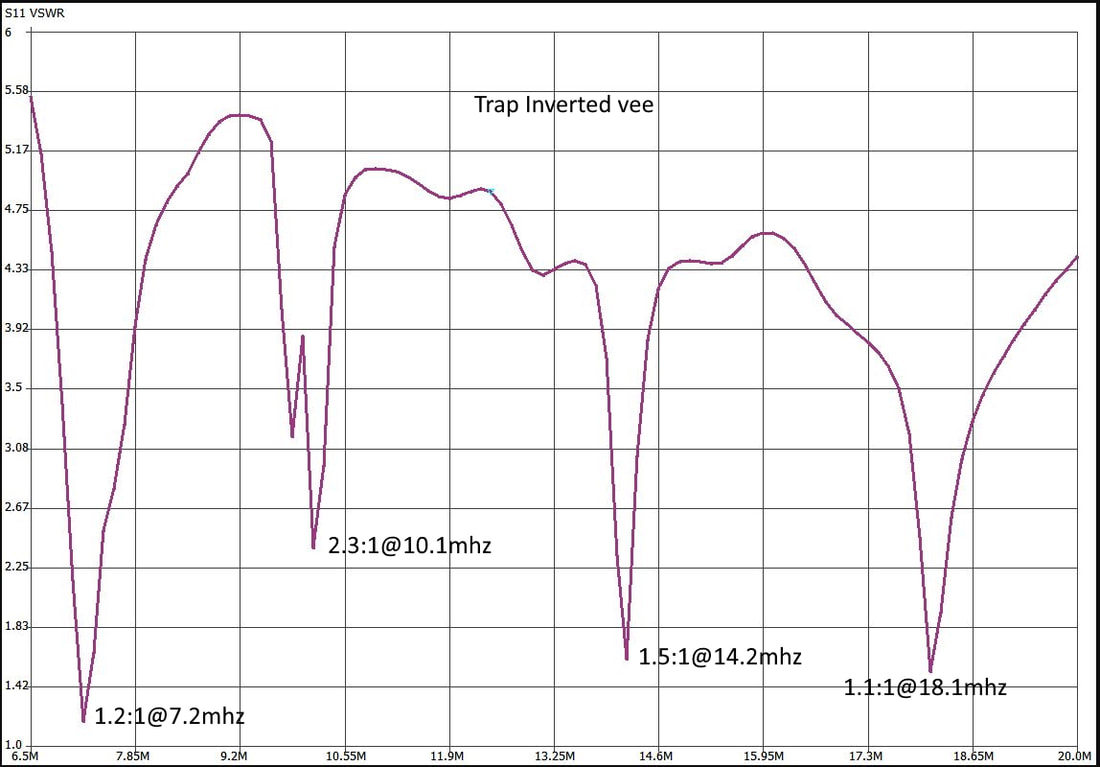
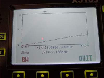
2020-01-01 The chart at right has been bothering me from the first time I saw it. The thing I couldn't figure out is why the SWR curve of the 30 meter segment was so scrappy instead of clean like the other ones. In fact it looks like it has two dips or resonance points right next to each other. So today I decided to investigate.
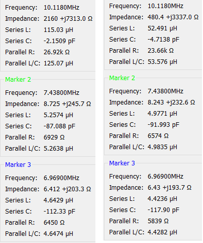
I took it down, removed the 30 meter traps from each leg and looked at them with my NanoVNA.
|
I believe the data chart tells the story. The two traps do not resonate at the same frequency. In fact they are separated quite a bit. That is evident when looking at the impedance figures. The one on the left presents over 200 ohms to a 10.1 mhz signal whereas the one on the right only presents 480 ohms impedance. So I need to investigate that further and try to get them both on the same frequency, ideally 10.1 mhz.
|
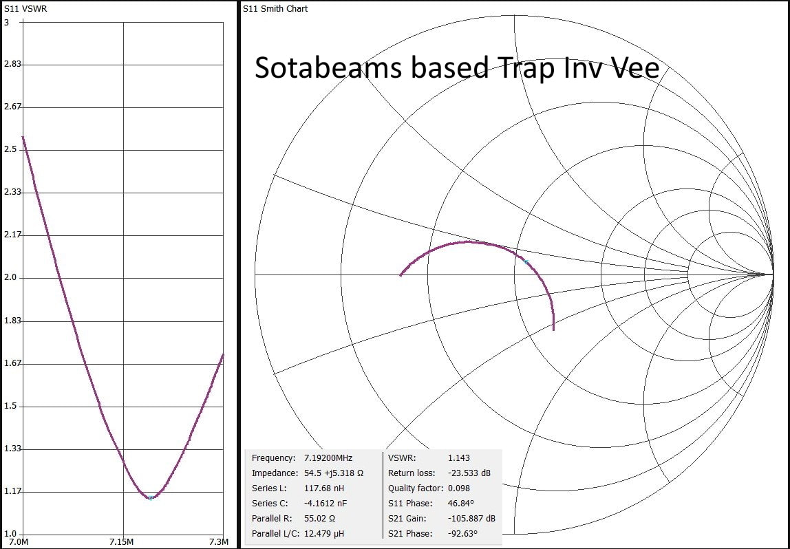
2019-12-19 Following is a perhaps helpful graph and data taken from the NanoVNA-Save software of my four band trap inverted vee using Sotabeams trap kits.
|
2019-12-17 Since getting my NanoVNA I've been "testing" every antenna I own, for fun and to become familiar with the NanoVNA. So of course I had to put this trap antenna up and have a go at it! In spite of the fact that it was in the 20s with about an inch of new snow on the ground!
As described below the antenna is supposed to be trapped for the 40, 30, 20 and 17 meter bands. And it is close!
The 17 meter band could probably be tweaked a bit. but overall it is not bad, especially considering the primitive test equipment I had available to tune the traps when I built it!
|
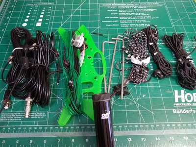
2019-10-23 After making and using many other antennas since last playing with this one over a year ago, on Saturday I dug this one out of a pile and strung it up. It's a good antenna! Easy to put up using a fiberglass 20' push up mast. And it seems to perform as well or better than my 40-10 EFHW. I made ten contacts with it all but two SSB on 40 meters. One, also on 40, was CW and another CW one was on 30 meters. All were at 20 watts using my Xiegu G90 transceiver. The most distant one was the 30 meter one at 1436 miles with a station in Idaho. Fun to have a little variety in my antenna life! Now I think I'll take it down and put up my 29 ft end fed!
In brief, this antenna is similar to a link four band inverted vee with resonant traps in place of the insulator/alligator clips to add or remove antenna segments to change bands. The advantage is simple band changing, just switch to a new band and start transmitting, no tuning, nothing. The disadvantages are two: 1) labor intensive to build and tune, 2) somewhat narrower bandwidth on each band, though that doesn't appear to be a major thing as I was able to get usable SWR across all four bands. But I warn you, be prepared to spend hours cutting, soldering, adding, checking SWR and doing it all over again. The primary advice I have is to have some sort of antenna analyzer on hand with fresh batteries! Next, start with the highest frequency band and work toward the lower frequency bands and it will go relatively smoothly, even if time consuming.
2019-03-18 Today I discovered that the ground has thawed enough to get tent stakes in the ground so I put up one of my push up masts and played with several antennas including my four band trap inverted vee. It seemed to work but the resonant frequency, especially of the 30 meter segment is way too high. Not too sure what is happening as the SWR looks quite a bit different from the last time I played with it. I was getting tired of antennas so kind of gave up for the day. It's possible I have the ends quite a bit higher than previously. So tomorrow I'll experiment with that.
|
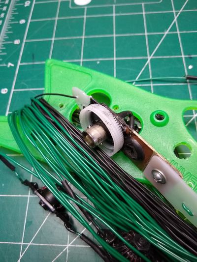
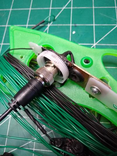
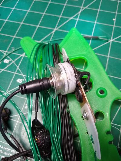
2018-11-09 It's way too early in the day to be doing this but an hour or so ago I made an attempt to waterproof the BNC connection at the center insulator of my trap inverted vee. I affixed a drink bottle cap to the underside of the insulator with Liquid Tape. Then I cut just the top of the drink bottle off to use as a skirt to keep the water away from the connector and cable.
|
To use it I'll slip the skirt over the coax (threads up), attach the BNC connector and then carefully twist the sirt into the lid. My theory is that any rain water that comes down over the edges of the top will collect, then drip off the skirt and NOT find their way onto and into the BNC connector. Time will tell. Since the traps are coated with Liquid Tape they should be waterproof.
2018-11-08 Well, as of this afternoon I've had two 40 meter QSOs with the antenna with good reports both way. Given that we have snow, albeit a small amount forecast for tonight and tomorrow morning I took it and the Shakespeare TSP20 Six-Piece Wonderpole mast down. The antenna and mast would do just fine but I'm concerned about the coax. Water could easily get into the BNC connector at the antenna center which would likely seep into the coax itself and might cause it to corrode. I guess it is a fair weather antenna at the moment. I'll think about that and come up with a solution.
2018-11-07 I can't say that I recommend building one of these. Not that I don't think it is a good antenna, I actually think it IS a good antenna. I say that with minimal on-air testing. I've played enough with the dual band trap antenna to think it will work well. But... the work involved in tuning the traps and then trimming the segments is close to insane, at least the way I did it! In fact the 30 meter element is still a bit shorter than I'd like but it covers all four bands with an SWR below 2:1 and most way below 2:1 so I'm done! Another reason I'm done is that the temperature is in the 30s with wind and an inch of snow is forecast for tomorrow evening with temps in the 30s for the high for the next seven days!
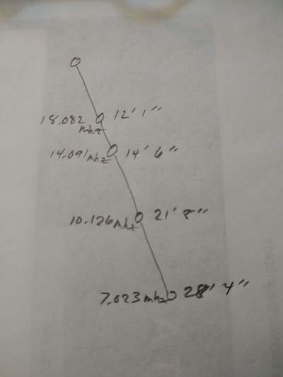
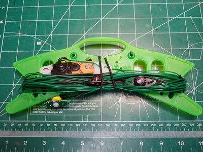
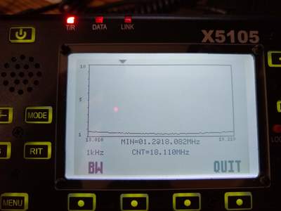
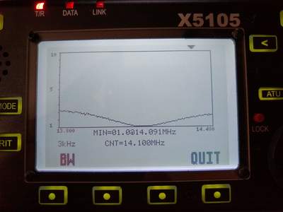
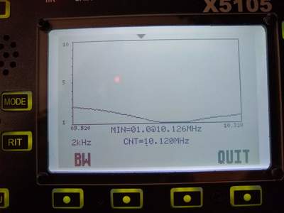
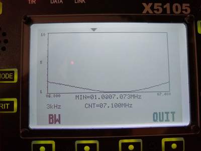
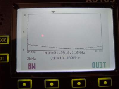
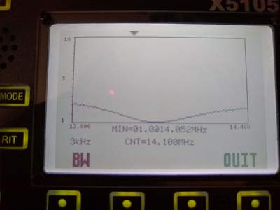
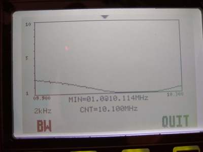
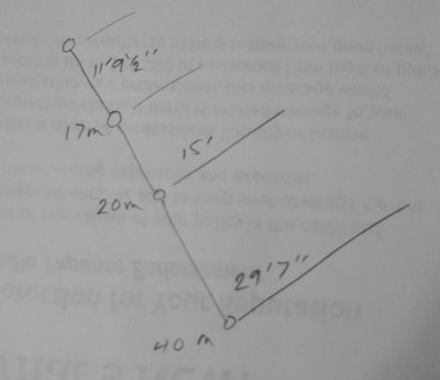
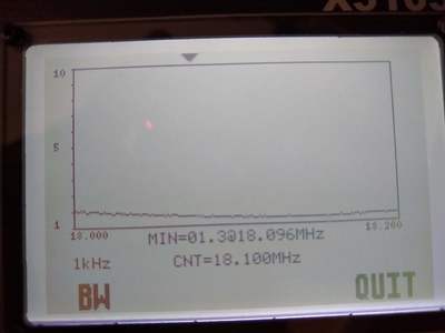
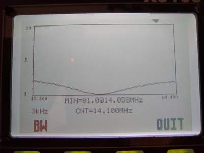
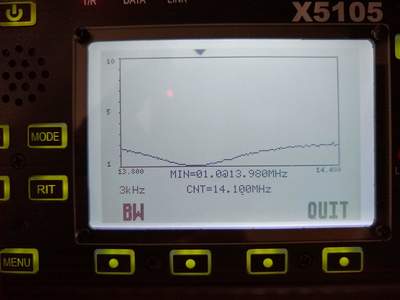
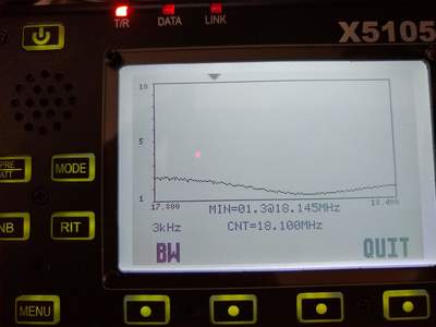
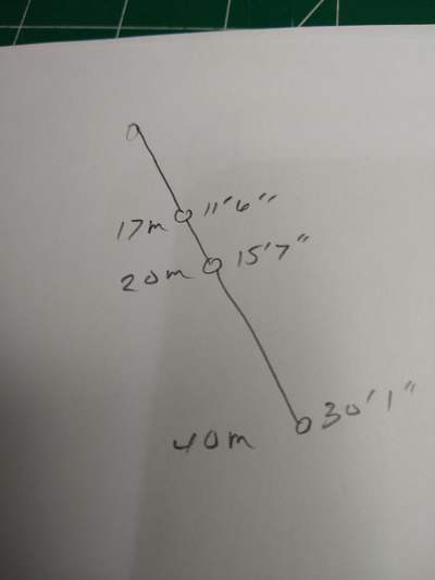
Below are my photos of the SWR scans and a sketch of the final measurements. All wound up as shown it weighs 4-1/5 ounces. Hope it helps someone.
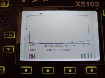
2018-11-05a Later today I built the 30 meter traps and tuned them to approximately 10.01 Mhz using the same test setup I used on the other traps. I also checked the 20 meter traps to be sure they were tuned to 14.0Mhz as recommended which they were. I then cut the 40 meter extension at 21 feet and inserted the 30 meter traps. Then I measured the SWR which is shown below. As the scans show 18 and 20 meters didn't change much. And 30 meters is actually pretty close to the design frequency. But 40 meters is way low. The inductance added by the 30 meter trap means that the 40 meter extension needs to be shortened. The weather declined so I had to take it down and was unable to do any further changes and testing. Perhaps tomorrow. In adding the 30 meter traps I discovered that I had the 20 meter traps located roughly six inches off from each other. I fixed that after the weather fell apart so my 20 meter lengths may have to be adjusted again!
As I stated below, it takes a lot of trial and error the adjust a multi-band trap antenna. If I were being paid $10 an hour for working on it I've probably spent at least a $500 on it! Maybe buying an antenna isn't such a dumb idea after all! :-)
2018-11-05 This morning I finished "tuning" the 17, 20 and 40 meter legs and traps on my soon-to-be four band trap inverted vee. The result is in the photos below which show the lengths of the wire from the center insulator to the traps and tip of each leg. The photos also show the SWR bandwidth's for each band. Next I'll assemble and tune the 30 meter traps and insert them into the current 40 meter legs.
2018-11-02a Well, I learned something today. If you are in a hurry when you make a change, like changing the length of the legs of an inverted vee and when you test it something doesn't seem right? Likely something is not right! When I tested my last trim cut to the new 17meter leg I was puzzled and frustrated that the frequency of resonance didn't decrease as it should have since I lengthened the leg, in fact it increased ever so slightly. Frustrated and getting late I decided to take it all down, put it away and look at it another time. As I cleaned up my work bench where I had trimmed, added, etc., there was the three inch piece I intended to put onto one of the legs between the trap and the center insulator. So I checked the antenna, sure enough! I had added the 3 inches to one leg but forgot to add it to the other one!!!! Too late to fuss with it any more.
|
I learned something else too. Tuning a trap antenna is time consuming!
2018-11-02 I strung up the antenna this morning and checked it out. I had to adjust the location of the traps in my 20 meter segment and then tweak the resonant frequency of the traps but it seems to work about right now. I adjusted the windings on the toroids so the resonant frequency of both traps is right at 18.05Mhz. Now to remount everything and do a final check. If all looks good I'll start on the 30 meter traps.
|
Below are the SWR graphs of the antenna for all three bands as well as the actual lengths of the segments. I have not adjusted the 30 and 40 meter segments. I'm not completely happy with it as the resonant frequency of the 17 meter segment is a bit high. It is live-able but higher than it really should be. But if I add wire to it, the other bands will be shifted somewhat lower and they are already toward the low end. See the original 40/20 trap antenna for comparison. That is one of the challenges with a trap antenna. ANOTHER, as I've stated before, are the narrow bandwidths of all of the bands thanks to the traps. The link version is an overall better antenna but in exchange for that you add the more complicated band changing situation.
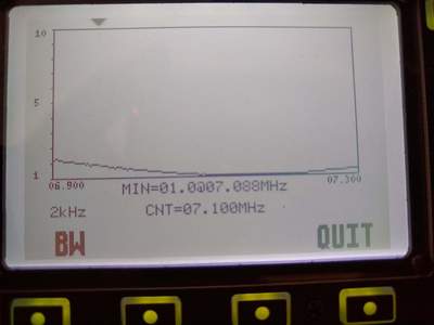
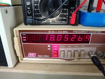
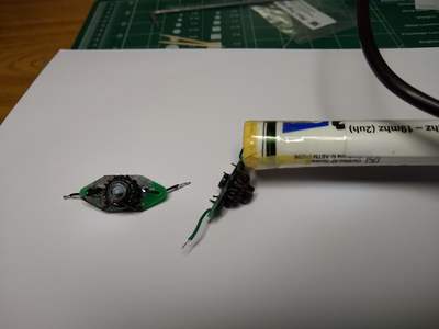
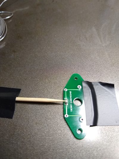
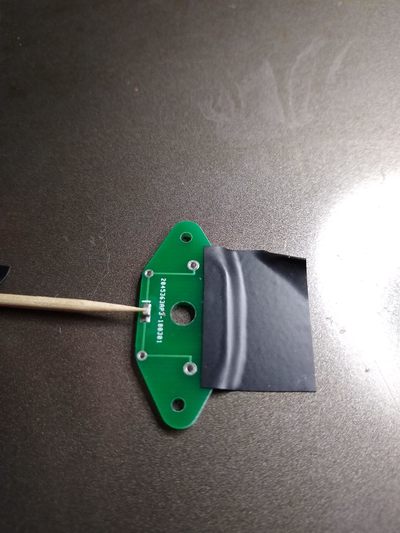
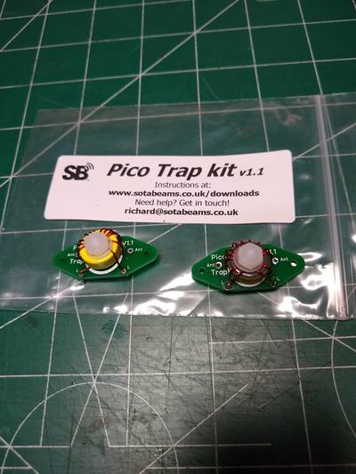
2018-11-01 My Pico Traps from SOTABEAMS came in the mail today so late this afternoon I built them. Building them just involved soldering the tiny surface mount capacitor to the circuit board, winding 13 turns of wire onto the toroid, soldering the toroid leads to the circuit board and testing/adjusting for resonant frequency. These are for 18 Mhz (17 meter band) so I adjusted them to about 18.20Mhz.
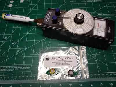
The trickiest part for me was measuring the resonant frequency. All I have to work with is a "dipper" which acts like the old grid-dip-meter of the past. It's one I built several years ago based on an FET transistor circuit I found someplace. It actually works pretty well but its frequency dial is "accurate" but only to about 100khz or less! Fortunately it has provision for connecting it to a frequency counter and the signal level is adequate for the old antique counter I have. It took some fiddling but I think I have them about right.
It was a fun little project. Now to add them to my current 40/30/20 trap inverted vee and see what happens. I think I have decided to do that, modify my existing one rather than start from scratch. It will be interesting to see how much I have to adjust each segment to make all the bands turn out as hoped. Keep your fingers crossed!
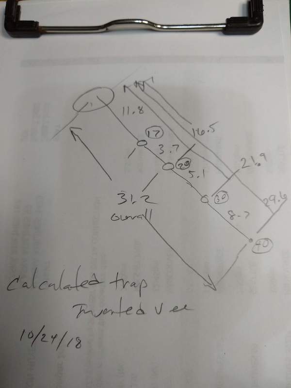
2018-10-24 This whole undertaking is based on my positive experience with a 40/20 meter trap antenna over the past few months. As a starting point I went online to an article which includes a calculator for dipoles and inverted vees. Using the inverted vee calculator for each band I came up with the initial lengths of the leg segments for my antenna which are shown below in the sketch. The resonant frequencies I chose for these calculations are 18.1mhz, 14.15mhz, 10.120mhz and 7.125mhz. They generally favor the CW segments of the bands as that is my preferred QRP mode. I should note that I am also thinking portable for this antenna so will be using #24 pr #26 wire and the very light weight Pico Traps from SOTABEAMS. Now to start making it.
|
My current thought is to cut the 20 mhz segment of my 40/20 meter trap inverted vee and insert the trap for 17 meters. After I play with that and if I'm happy with the result, I'll cut the current 40 meter extension and insert the 30 meter trap.
The leg and total lengths of my 40/20 version are somewhat different from the calculated legs and total length of the proposed one so will have to think about that prior to cutting anything. Part of the challenge.
Probably a wiser approach would be to mock up and trim the whole thing from scratch using inexpensive RCA #24 speaker wire. Then when I have it figured out I can make the "live" one by either modifying my current one or making a new one.
|
