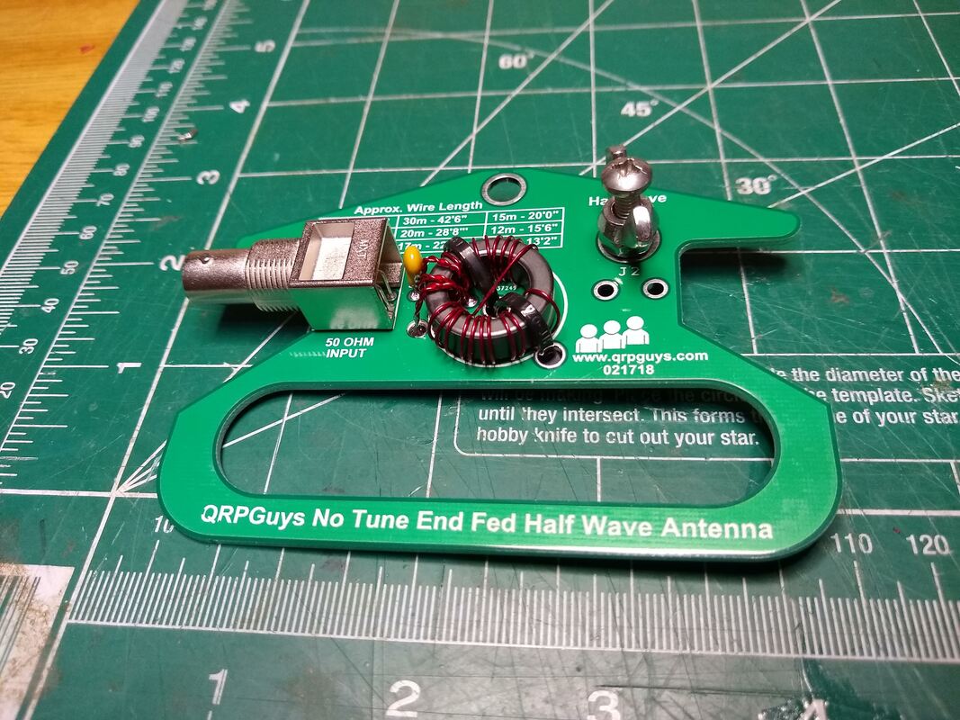
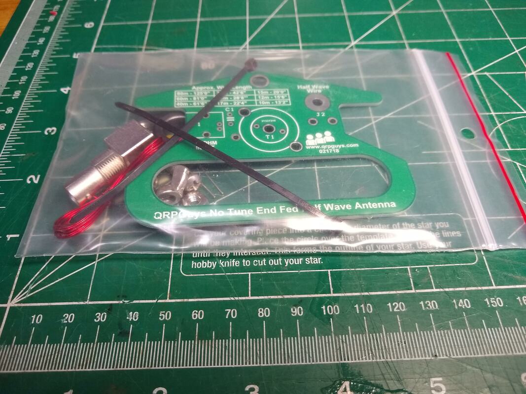
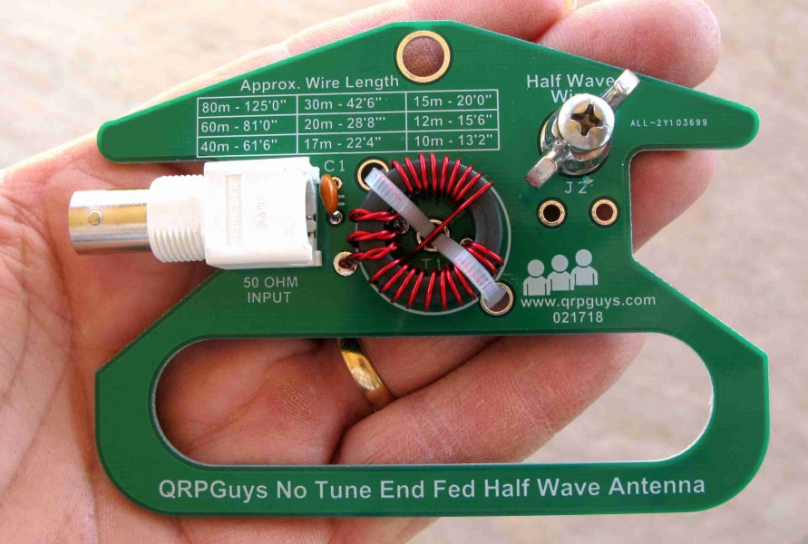
Building/Using an End Fed Half Wave Antenna - EFHW |
My notes below are arranged in reverse date order with the most recent at the top. So to follow my experience chronologically, start at the bottom!
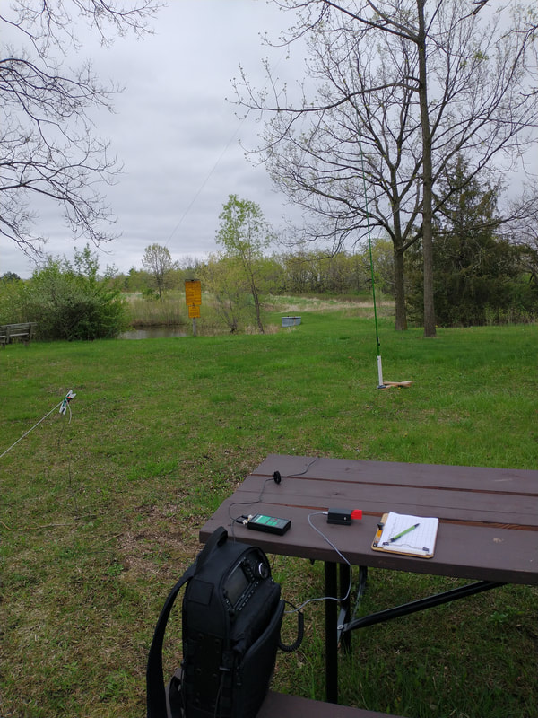
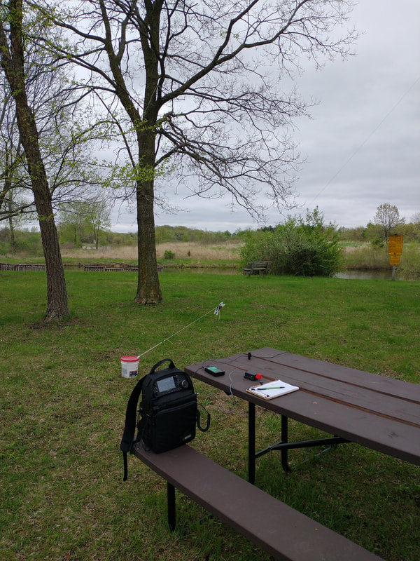
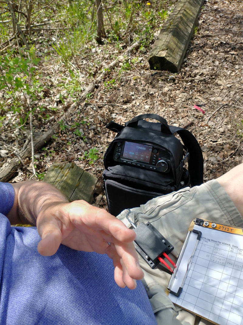
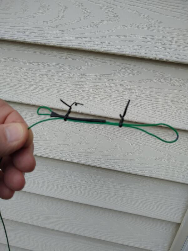
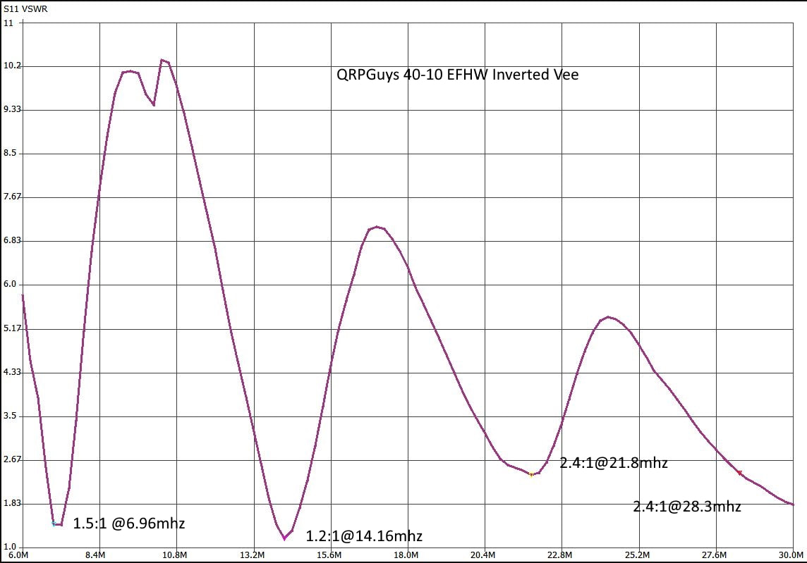
2022-03-05 Yesterday afternoon it was about the second almost warm day here in southeastern Wisconsin this year. It was about 58 and sunny. I grabbed my ic705, KM4ACK EFHW antenna and headed to K-4265 just a few miles from home. Found a picnic table not too far from the parking area and set up. I put the antenna up as an inverted vee, the way I always do. As I was driving out I decided to work as many bands as possible CW. So I started on 40 meters. It was alive from the start and I quickly got twelve contacts. Then switched to 30 meters. That was easy to do because I have put a 30 meter link in the antenna. Going was a bit slower but got four contacts pretty quickly, then it dried up. So I went to 20 meters by closing the 30 meter link. Got twelve contacts without too much difficulty including three from Europe and one P2P. Then I tuned to 15 meters and called quite a while. No takers, so I opened the 17 meter link and after a bit got two contacts including one in the Dominical Republic.
What's my point? With just a bit of work while making the antenna and less when using it, the humble 40 meter EFHW antenna can be used happily on 40, 30, 20, 15 and 17 and 10 meters. In other words, it really can be an effective nearly all-band antenna. Yes, you do have to lower it to open and close the links. But that is a fairly low price to pay for a good multi-band antenna. And yes, you will need to fuss with it to find the locations for the links. But for me, it was worth the trouble!
2022-03-05 Not all EFHW antenna's are created equal. Probably not a surprise to anyone, but perhaps still worth mentioning. I have at least three of them: QRPGuys, KM4ACK and more recently the one by K6ARK. I've used all three under several different circumstances. Whether they differ in their radiating performance I can't say. I've made quite a lot of contacts with them all, 554 with the QRPGuys, 204 with the KM4ACK and 20 with the K6ARK one. In fairness, I've only had the K6ARK one for a month today. But an experience over the past few days has made me pay more attention to their differences.
What I like most about the K6ARK one is its extremely small size. It is very much a shirt pocket antenna. Next in that regard would be the QRPGuys one. Not much larger or heavier. The largest is the KM4ACK one. Mind you none of them are large. They have different sized toroid's which match their size which probably translates into power handling capability, around 10 to 15 watts for the two smaller ones and somewhat more for the KM6ACK.
What brings this up now is that yesterday I headed out to K-4265 Richard Bong State Recreation Area not far from my home to enjoy the warming weather and play some POTA. As my primary antenna I took the K6ARK EFHW. When I had it set up as an inverted vee And checked the SWR on both 40 and 20 meters it was above 2:1 and caused my IC705 to limit its power to about 5 watts. Had I brought my Elecraft T1 tuner I would have just used it. But instead I switched to my backup antenna, a DIY 9ft loaded vertical and all was well. But I was puzzled since I've used it previously. Today, here at home I decided to see what was up.
Both the k6ARK and the QRPGuys ones were resonant just outside of both bands. So I set up the KM4ACK one exactly the same. It was resonant across both bands as well as on 15 and ten meters. And with the links I had added to it also was resonant across 30 and 17 meters! All three showed excellent SWR at their resonant frequencies.
What did I learn? Know your individual antennas so you don't get a surprise in the field. I'll likely take the KM4ACK most of the time, if I don't have my tuner with me! And I may spend some time tweaking the other two as their are times I really want their small size.
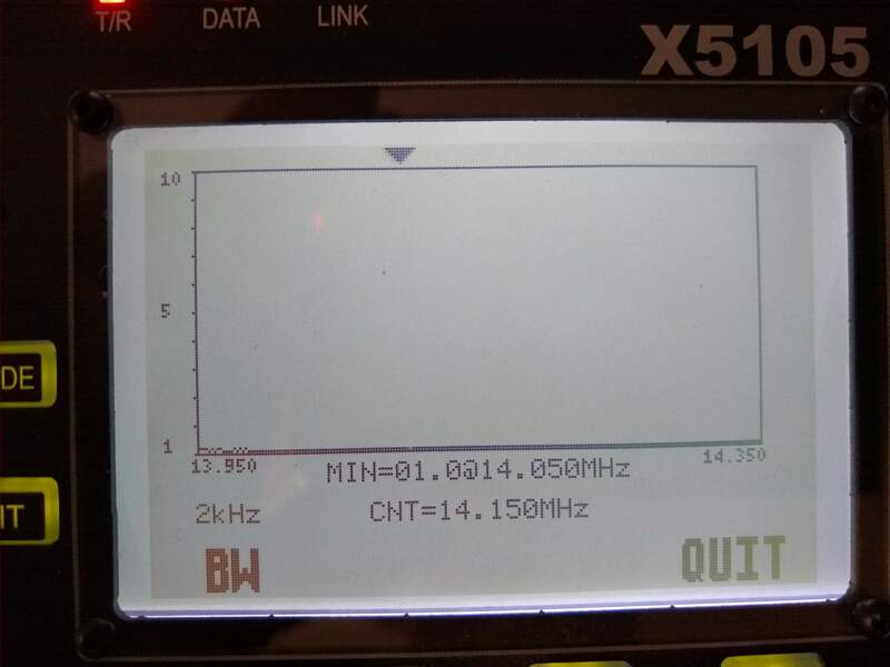
2022-02-04 Late this morning, when the temp reached about 20 deg I swapped the element from my QRPGUYS EFHW antenna to my just completed K6ARK EFHW transformer and put it up in the driveway as an inverted vee with a 20' fiberglass pole supporting the center. Surprisingly, the SWR on 40 and 20 was well below 1.5 to 1. I worked two stations on 40 including in n8yo in k-1500. Then I opened the link for 30 m and got one more QSO. It was about a 10-minute ragchew. If you take into consideration the radiating element and something to wind it on there isn't that much difference in weight or convenience between the K6ARK and the qrp guys antenna but the K6ARK is clearly the best looking! During the QSOs, I had the antenna connected to my x5105 via a 30 ft rg316 coax. But then I took the radio outside and connected the transformer directly to the radio. I didn't see any difference in the SWR. It was too cold to actually operate standing there.
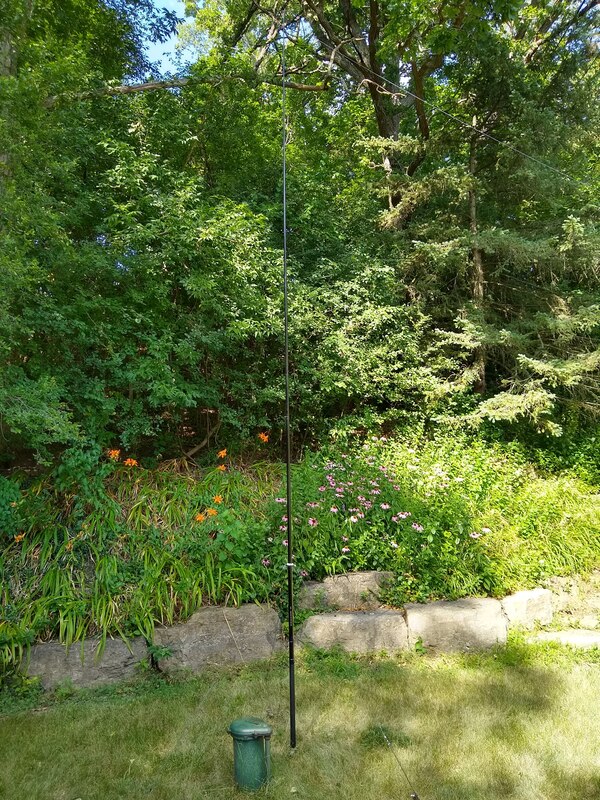
2021-12-03 Most of my EFHW uses, particularly POTA (Parks on the Air) activations, have been with my EFHW antenna set up as an inverted vee. That is, the approximate center is held aloft by one of my fiberglass collapsible masts with both ends sloping down near the ground. That's convenient and quick, only requires one support point and seems to work well. I've tried a sloper configuration which also works but it's hard to get a good angle with the driven end a few feet off the ground rising to 20 or 30 feet at the other end, 65 ft away.
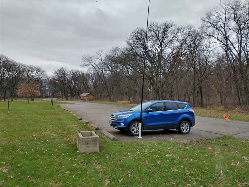
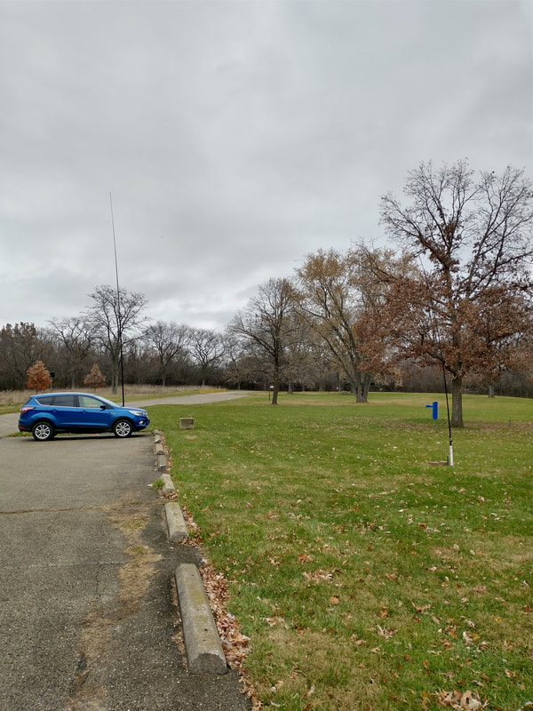
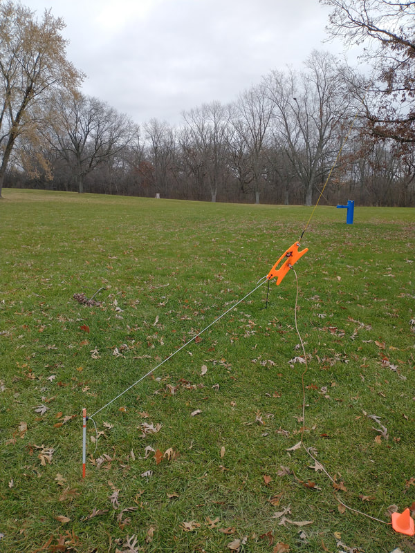
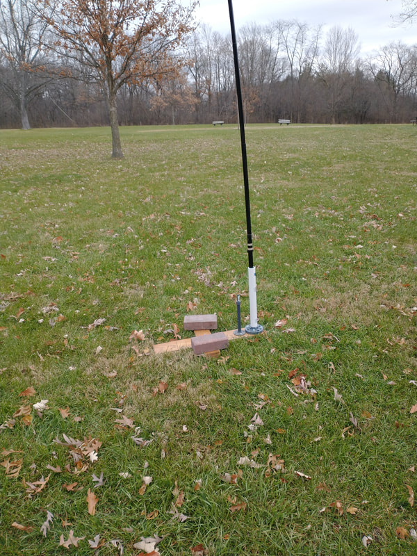
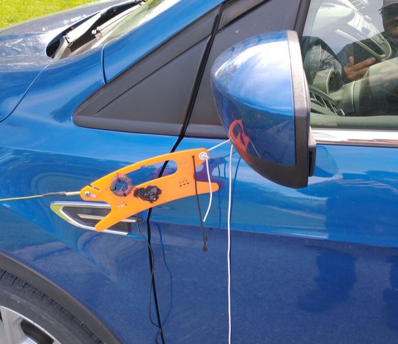
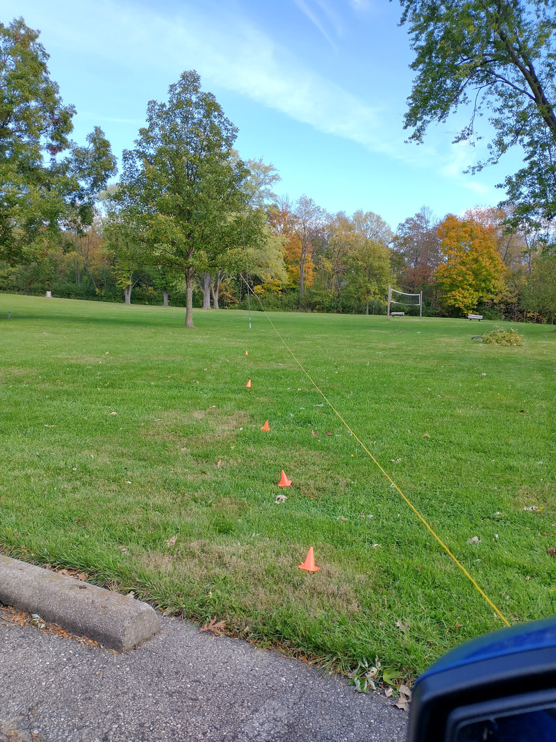
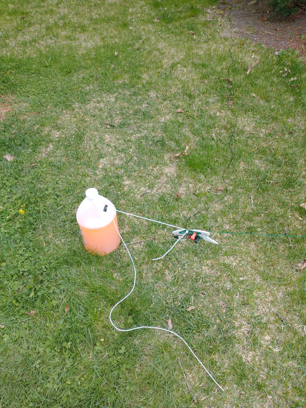
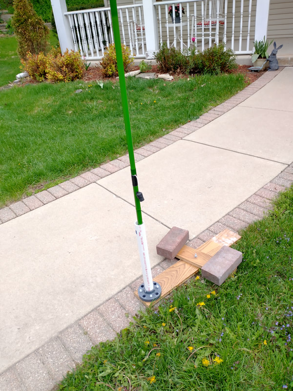
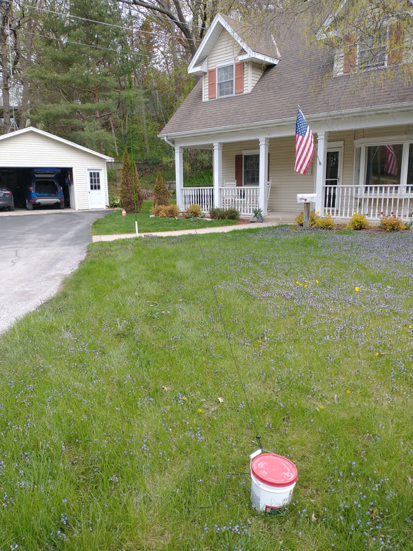
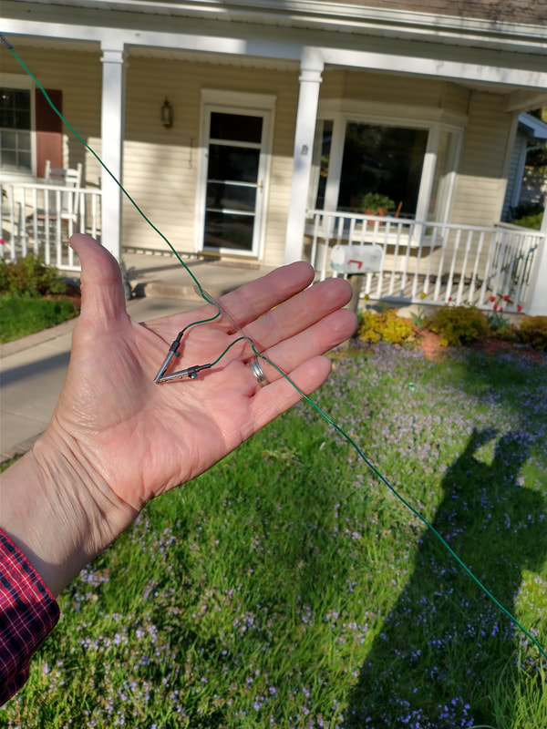
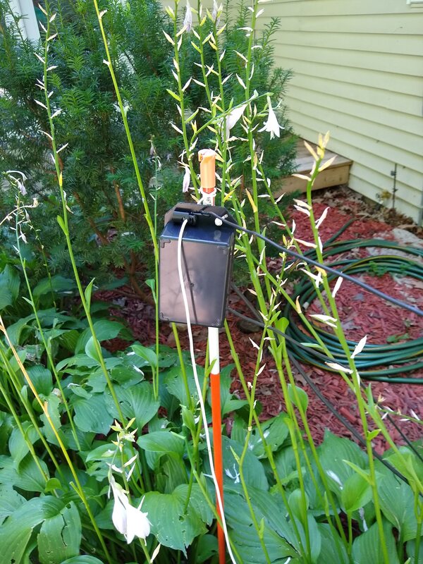
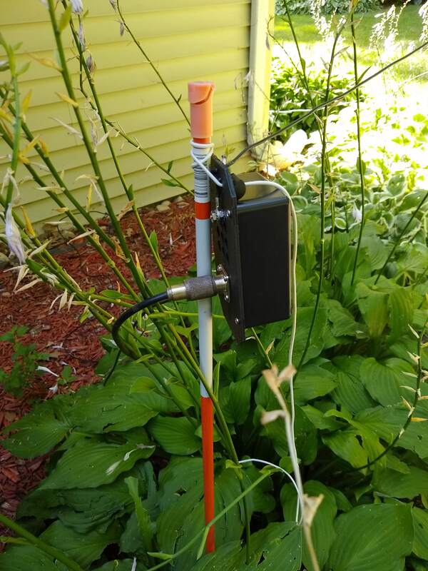
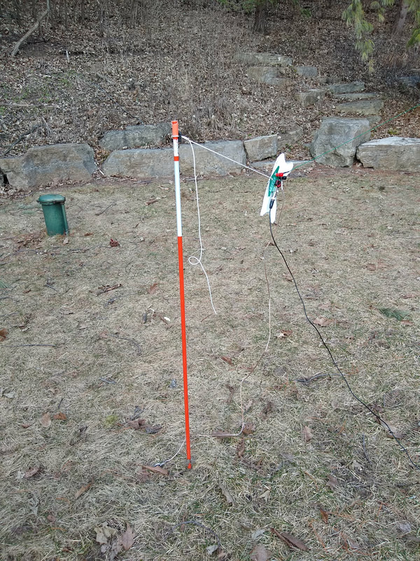
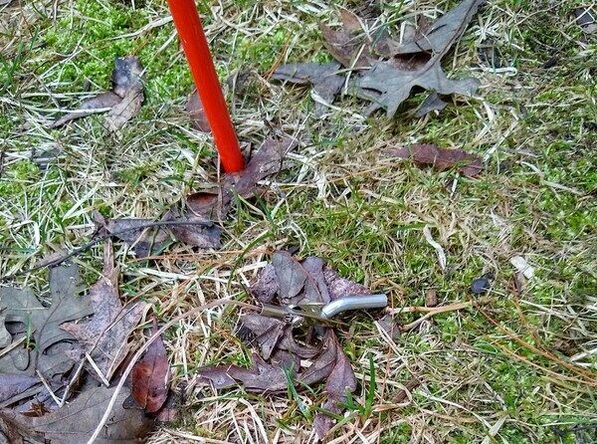
Since I got my 32 ft Spiderbeam mast I decided to play with an inverted L configuration. I put my DIY drive on mount under a front tire of the car supporting the 32 ft mast. Then I set up a 20 foot mast 40 or 50 feet away in a free standing support. I tie the transformer to a snow stake about 25 ft from the car and run the wire up through a loop at the top of my 32 ft mast and out more or less horizontal to the 20 ft mast. I tie both ends off with 1/8 in bungee or shock cord. Both times I've used it that way at a park nearby (k-1440) I got great on-air results on both 40 and 20 meters. Setting it up is a bit more work than the Inv vee approach but still pretty quick.
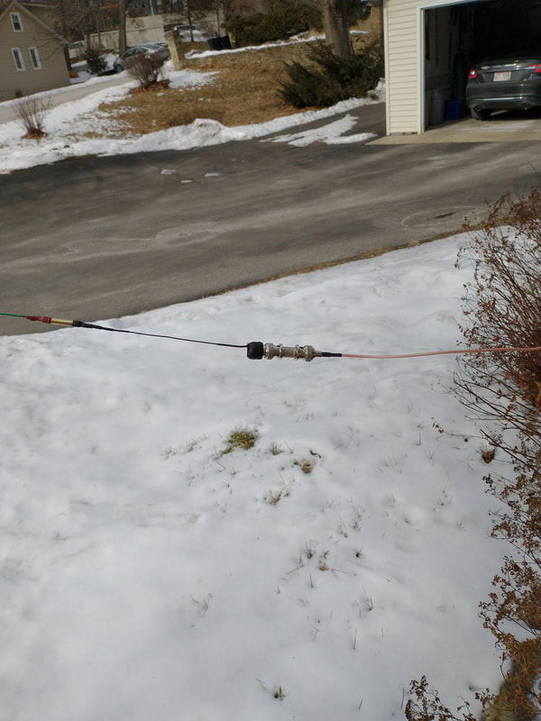
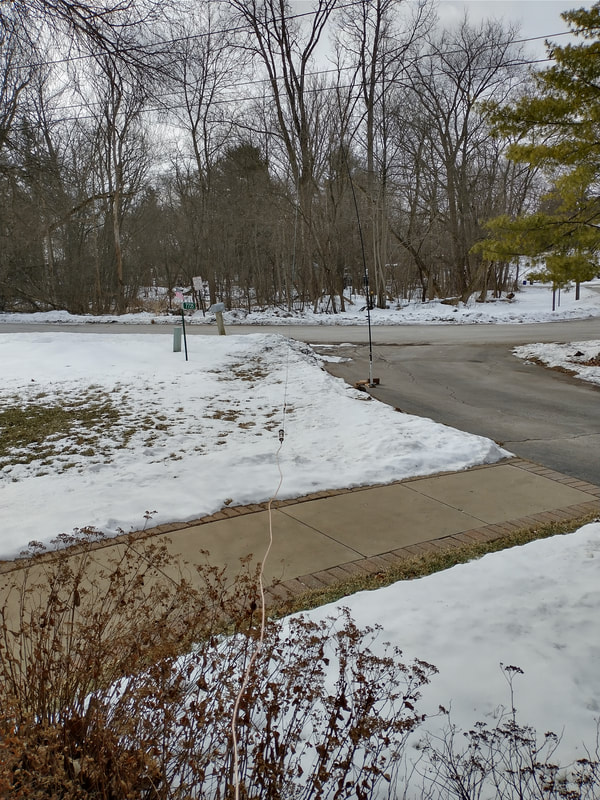
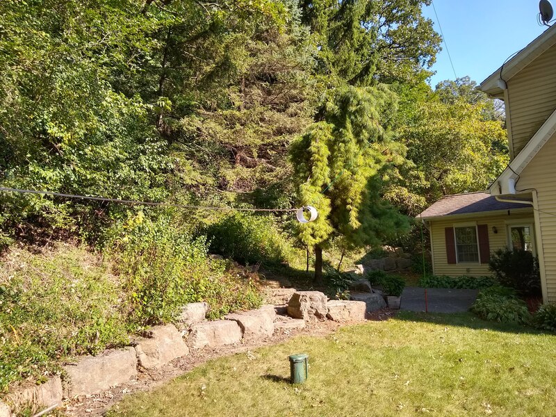
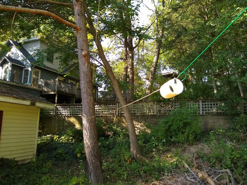
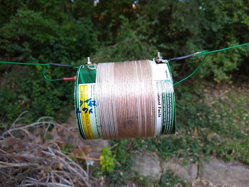
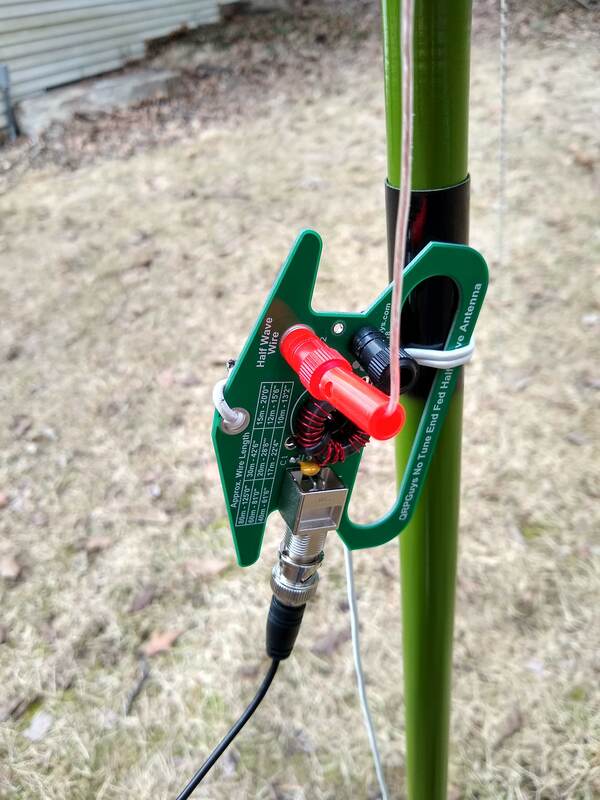
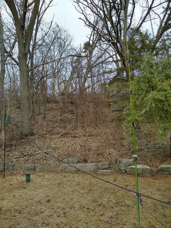
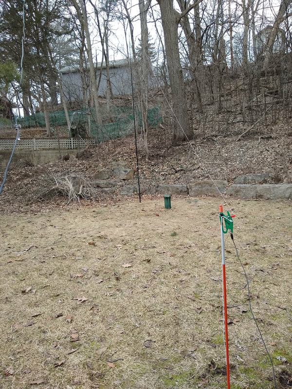
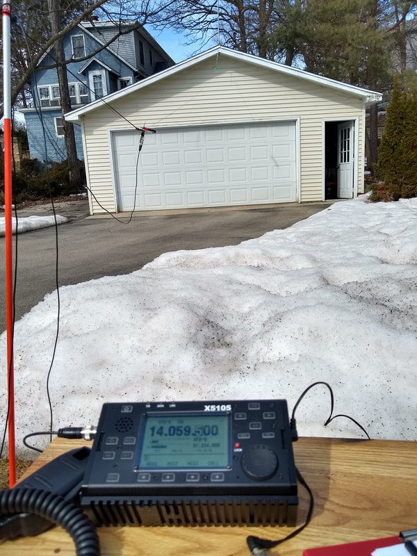
The phiotos below, L to R, show the view from driven end, the view from the far end, the transformer/winder tied to the snow stake, and the far end mast support.
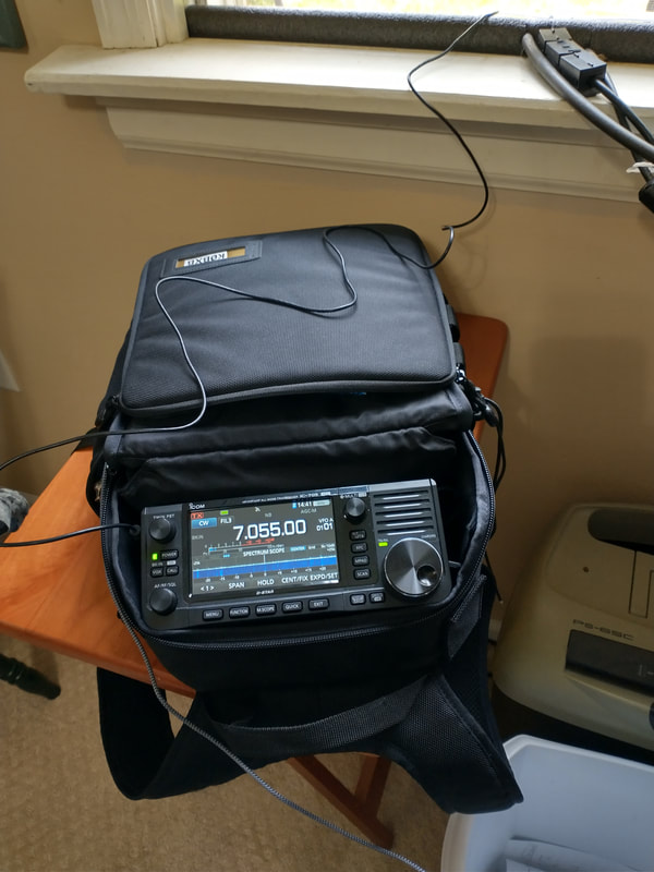
I drive it with my ten watt IC705 using RG316 coax. I have several EFHW antennas, the one pictured is by KM4ACK.
2021-08-04 Had 21 POTA contacts this morning with my 40-10 KM4ACK EFHW with links for 30 and 17 meters. I was activating k-4265 Richard Bong State Recreation Area in southeast Wisconsin. One on 17m, six on 30m and fourteen on 20m. All CW at 10w with antenna set up as an inverted vee. One of the 20m ones was with a station in Hungary. Thanks everyone.
|
2021-10-26 Today used my KM4ACK EFHW and ic705 to activate k-1440 here in SE Wisconsin. 40 meters was relatively short but good. 23 CW contacts in a half hour.
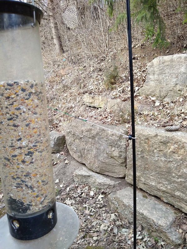
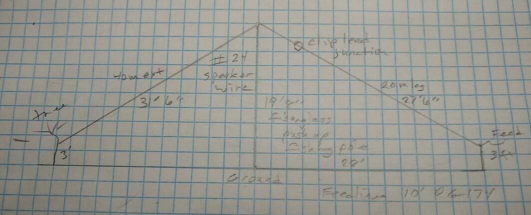
Afterthought: As I entered my contacts into my HRD log I noticed that ALL of them were in the less than about 500 mile range. It hit me that mounted as a sloper pretty close to the ground it was really a NVIS antenna and as such performed very well. The far end was supported by a 20' fiberglass push-up fishing pole leaned up in the tree. |
|
2021-08-02 A couple days ago I took my IC705 and the KM4ACK 40-10 meter EFHW to my favorite park, K-4265 Richard Bong State Recreation are about ten miles from my home here in SE Wisconsin. The antenna performed exactly as I expected based on my tuning it up at home. It and all 40-10 meter EFHW antennas has one potentially significant drawback. They don't work on 30 or 17 meters without a tuner. With propagation improving I especially miss 17 meters.
Some time ago I added a link to my QRPGuys EFHW which I have used often. So today I decided to not only add a link for 30 meters but also one for 17 meters. Conceptually, that is easy to do. But even using a NanoVNA it took me most of the afternoon to find the correct places to cut in the links. So I don't want to minimize the work and time involved but for me, being retired and going to a park to work POTA a couple times per week, it was worth the time. Now it truly is a "multiband" antenna, covering 40, 30, 20, 17, 15 and ten without needing a tuner. Haven't used it on air but based on my experience with the QRPGuys one, I'm confident it will work.
|
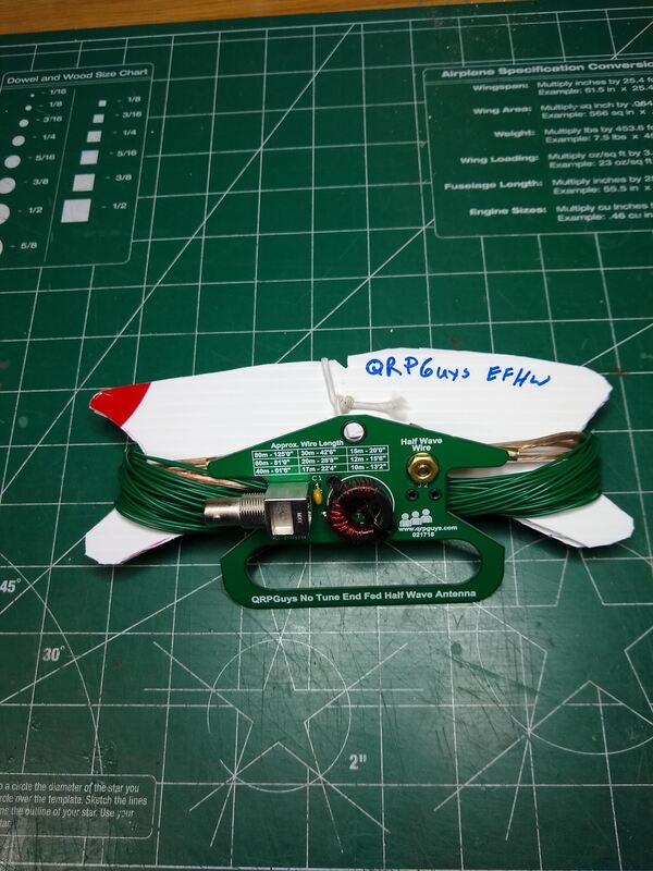
2021-07-31 I've been using QRPGuys no- tune EFHW antenna for a couple years on 40 & 20 and like it a lot. Even added a 30m link in it.
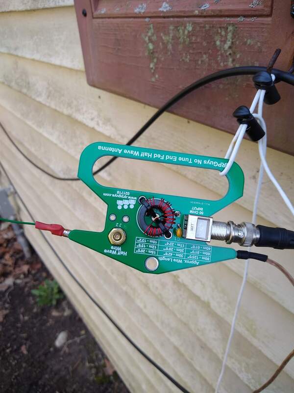
A week ago I saw something about KM4ACK's EFHW kit and got one. I'm impressed with the simple, compact, light weight and complete design. Today I compared them with my NanoVNA by stringing up first one then the other as an inverted vee keeping the support, coax and tie off as unchanged as possible.
My first observation was that the KM4ACK one was 9ft longer 68ft vs 59ft. After scratching my head a while I noticed that it's coil secondary had a total of 14 turns vs 24 turns. Less inductance means longer radiator.
Second the lowest SWR on the KM4ACK was somewhat lower and sharper on all bands.
Finally, the QRPGuys has kind of a double-dip SWR curve on 20m. I have two of them and both are like that. I may rewind one with the fewer turns used by KM4ACK just to see what impact that has.
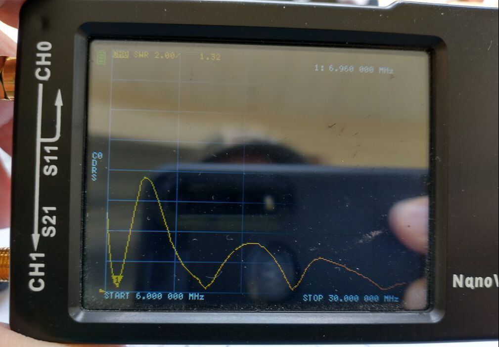
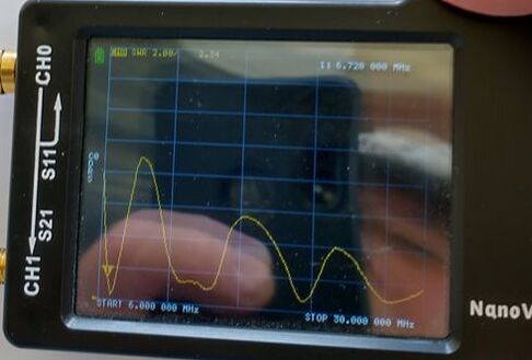
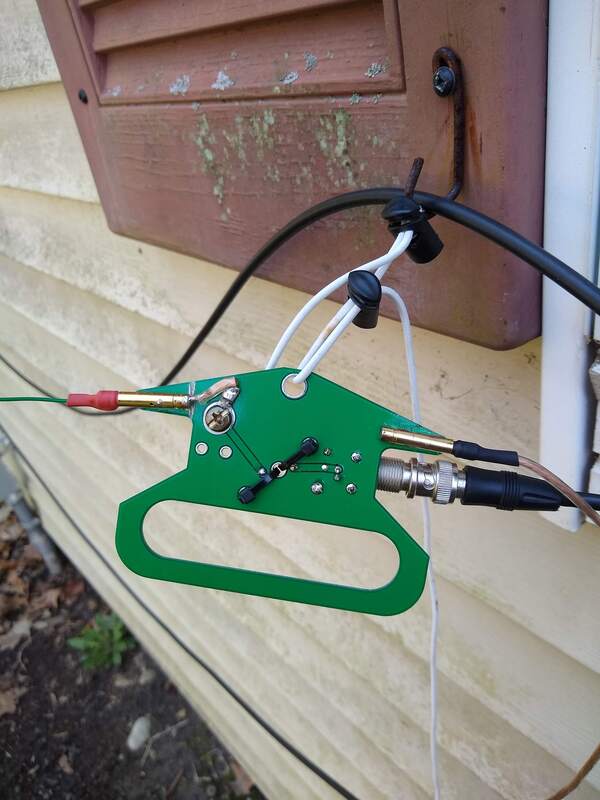
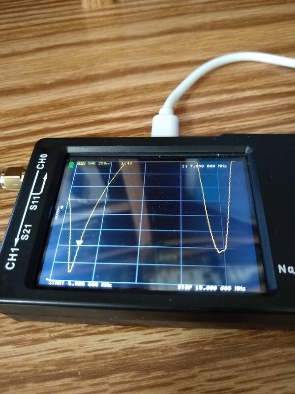
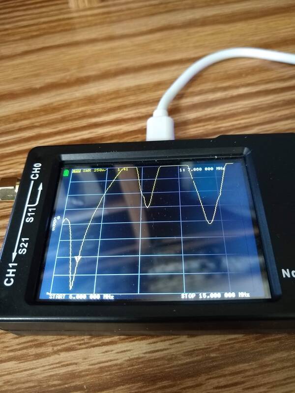
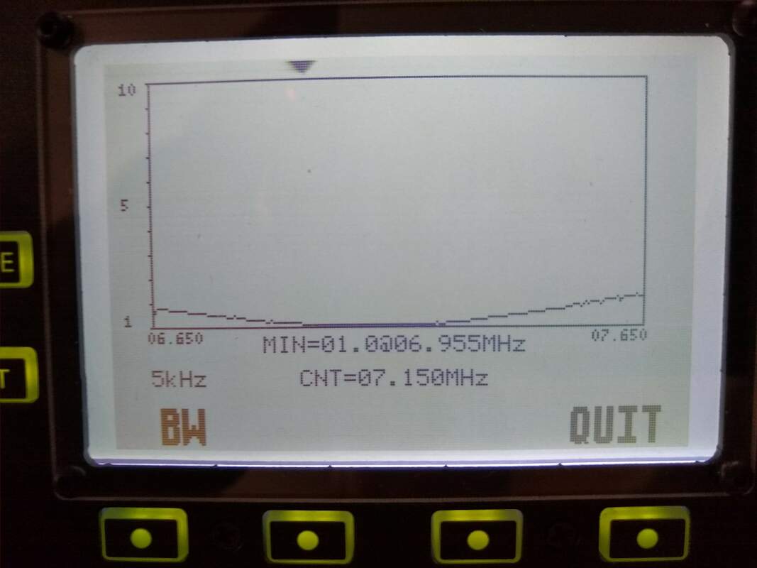
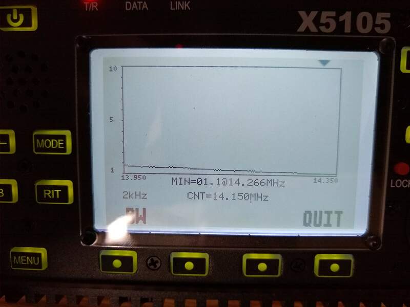
My purpose is not to bless or curse either antenna, just share my observations! I've had 551 contacts with the QRPGuys one and 27 with the KM4ACK one. They are both solid antennas, worth the money! The two photos were taken this morning. The left one is KM4ACK.
|
KM4ACK EFHW Antenna SWR
|
QRPGuys EFHW SWR
|
2021-05-04 Cool afternoon at k-4265 today, in the 50s and cloudy. But I had to test my 40/30/20 qrpguys EFHW again in the park. Worked perfectly on all three bands! Came home with 14 in the log. Conditions weren't great on 40 or 30 and I missed a few I just couldn't copy but thanks for trying. Used my IC-705 with the T1 tuner between it and the antenna but just put the tuner in bypass as it wasn't needed. I think my problem on Friday must have been the location, either how I had it set up or something about the location itself. Friday it was completely over a paved parking lot surrounded by trees. Today it was completely over grass with a new trees quite close but otherwise very much like my yard. The rig (except for the tuner which was in bypass). Everything was as close to identical as i could make it in all three locations, even the height of the ends of the antenna off the ground.
|
2021-05-03 POTA has a way of humbling one. Two days ago I inserted a link in my qrpguys 40 meter EFHW adding 30 meters as described below. I checked it out and made a contact on each of 40, 20 & 30 meters. SWR was "perfect" on all three bands. So today I couldn't wait to get out to K-4265 and and show the world how to do it! it was really windy but I found a relatively calm and vacant parking lot and quickly strung the antenna up as an inverted vee. Connected my IC-705 and checked out 20 meters. The SWR was high causing the radio to cut its power back. Checked 30 meters, same.
Forty was good so I settled in to fill my log. Over an hour later I barely got my 10 contacts. Had to call CQ SKCC on 7.055 for the last two!
I came home pleased but puzzled! But it was fun even though. The parking lot was near a bog so frogs entertained me a little! Sorry the photo isn't better. Sitting in the sun it's hard to do a selfie! So this afternoon I set it up in the yard again As I "feared" it was "perfect" here again on all three bands. Clearly there was something in the place or in the way I set it up that caused the problem. So I'll go back to a different location in the park and try again!
If are a detective and like problem solving, make antennas! But don't get all proud! Your antenna is watching you. :-)
|
2021-05-01 I've been using my QRPGuys 40-10 EFHW antenna for quite a while now, especially when doing a Parks On The Air (POTA) activation. It is relatively simple to erect and just works well on 20 and 40. Haven't done much with it on 15 or 10 as propagation is not very good right now much of the time and there is seldom any activity. I also have a Wolf River Coils (WRC) portable vertical with collars for 40, 30 and 20. It is another excellent antenna taking into account the advantages and disadvantages of a vertical. And I have a DIY wire version of the WRC vertical which works equally as well though is not free standing. The main "complaint" I have had with the EFHW is that it doesn't include 30 meters and increasingly I'm finding 30 meters productive. So the past few days I've been mulling over and then messing with making the EFHW work on 30 as well as 40.
The slickest solution would seem to be to add a 30 meter trap at the 30 meter half wave point in the radiator, about 42 feet. So two days ago I set about to do that. Using the QRPGuys trap kit I assembled and inserted one. Before adding the 15 ft or so extension for 40 meters I trimmed the radiator to give me resonance in the 30 meter band. But when I added the extension everything went crazy! It was too long for 30 meters and too short for 40 meters. No problem.... I set about adjusting first one and then the other lengths. Several hours and who-know-how-many trips between the antenna and the rig I got bored and gave up! I'm sure it can be made to work, but would cost the price of a pair of shoes!
Yesterday it occurred to me that using a link rather then a trap should be simple and should achieve my three band goal. So I did it. After finding the 30 meter length, I inserted a DIY link and then added to the other side of the link wire to make it a half wave long for 40 when the link was connected. Was actually pretty simple and quick. Then today, to make sure gremlins didn't mess it up overnight, I set it up using a 20 ft carbon fiber pole for center support and a jug of antifreeze for the far end and paint bucket for the driven end. SWR was "perfect" on all three bands.
I then "vowed" not to eat or drink until I had at least one contact on each band! So, using my IC-705 at 5 watts I set to work on 40 meters. Within a few minutes I heard W3IQ calling CQ SKCC. He was about 559. I called him. He came back immediately, giving me a 579. He too was QRP! One down!
Then I opened the link and checked 30 meters. SWR was 1:1! Not much activity on 30 so I called CQ. After about ten minutes K4WYin Virginia responded. We ended up spending 10 minutes in a nice QSO. Clearly the antenna was radiating!
So I closed the link and switched over to 20 meters. 20 was also fairly quiet with the only calls I heard being from Arizona in the Arizona QSO party or something. I tried calling several but got no responses. Then on 14.053 I heard N3RD calling CQ in the Pennsylvania QSO Party and gave him a call. He heard me and gave me the standard 599 but was 559 in here.
Whew, I was free to eat and drink again! I'm excited to get to a park and use it in a POTA activation. That won't be today as the wind is blowing constantly about 25mph with gusts reported around 50mph! After using almost entirely verticals for the winter months I'm looking forward to using this "new" EFHW.
2020-09-27 When I posted about this 80 meter modification to my QRPGuys EFHW antenna one fellow responded saying he too tried this but after playing with it a while tossed out the coil and simply used his tuner to tune the 40-10 meter antenna on 80 meters and used that. His "frustration" was the same as mine, very narrow bandwidth. Tunes great within it's 100khz range. Outside that you have to use the tuner anyway. So I tried it. My g90 internal tuner will tune the antenna across the entire 80/75 meter band just fine. But now the real question, is there any substantive difference in performance between the two options? I have not had any contacts with either option. Last night the QRN was so bad there was no use trying. So wondering....
2020-09-25b I think I figured out my problem. I was getting quite different readings on my nanoVNA and my xiegu x5105. RF on the feedline was giving me erroneous readings. That'll play tricks with you! I installed two clip-on ferrite beads with three turns of coax through each one. That seemed to clean everything up! In fact, the length of add on radiator after the coil is now 7' 8" like I expected it to be originally! The coil is 35 turns of RCA 24 gauge speaker wire, close wound iver 2-1/8" with a calculated and measured inductance of 79uh. That's below the 110uh which was my target. Not sure what that means to performance, etc. What I do know is that now
- SWR is 1:1 at 3.58mhz and the 2:1 SWR range is 3.54mhz to 3.65mhz. With the tuner I can cover all of the CW portion and most of the phone portion.
- SWR is 1:1 at 7.235mhz and is below 1.5 across the entire 40 meter band.
- SWR is 1:1 at 13.6mhz and SWR is below 2:1 across the entire 20 meter band.
- Furthermore, the antenna measures almost the same whether the coil and extension are on or off.
2020-09-25a OK, I think I am zeroing in on a design. I carefully tuned my QRPGuys EFHW so it had good SWR across 40, 20, 15 and 10 meters without the coil attached. Then I added the coil with a ten foot extension wire and a way to fold it back so I would have lots of room to adjust. The final adjustment ended up to be 9'2" when folded back on itself. Checking SWR, the resonant frequency of 40 and 20 was changed very little and it resonated toward the bottom half of 75/80 meter band but with my tuner it is usable across the whole band.
2020-09-25 Playing around this morning using my x5105 and nanoVNA I think I discovered that the nanoVNA has been giving me bad readings. Not sure what that is all about. Anyway taking the readings using my x5105 here is what I found.
Without the 110 uh coil
This is getting too complicated! Not sure what is happening but I may give it up for now. Clearly the concept works. But unclear what it would take to make it usable on all three bands.
Without the 110 uh coil
- 1.0 SWR at 6.8mhz (below 2:1 across the entire band
- 1.4 SWR at 14.0mhz (below 2:1 across entire band)
- 1.0 at 3.8mhz (shown on the sweep but radio wont' do full power anywhere on the band. Common Mode?)
- 1.0 at 7.1mhz
- 1.4 SWR at 13.5mhz
This is getting too complicated! Not sure what is happening but I may give it up for now. Clearly the concept works. But unclear what it would take to make it usable on all three bands.
2020-09-24 Pondering a canoe trip and POTA Activation in the Boundary Waters Wilderness Canoe Area of northern Minnesota in a couple weeks I have pretty much settled on taking a QRPGuys 40-10 EFHW and a QRPGuys three band vertical. I've been trying both out here in my yard for a while and am very pleased with their performance, weight and ease of use. But with Fall here and conditions significantly improving on 80 meters, I've been thinking about how to include something that will cover 80 meters yet now be hard to deploy. Then it occurred to me that some people add a coil and short extension to the 40-10 EFHW so it will cover at least some portion of the 80/75 meter band. So this afternoon I began experimenting with that idea.
My mission to find a suitable coil form led me to the Costco Multivitamin jar! It is 3-1/4 inch diameter and after looking at formulas it looked like it would take about 48 turns of 26 gauge RCA speaker wire to get the 110 microhenries that seem to be required. So, I cut the top and bottom off the jar (made from very light weight plastic) and wound the turns. Ended up requiring about 56 turns but I got it. Measuring the inductance was fairly easy by putting a 10pf capacitor in series with the coil and connecting it to CH0 on my NanoVNA. By simply scanning the SWR curve the dip was very obvious. With the resonant frequency and the 10pf in hand I entered them into an online Calculator, made a few turns adjustments and Bingo! 110 microhenries.
Next I headed outside, strung up my EFHW and sloppily attached the coil followed by about 8 feet of speaker wire to the far end. The NanoVNA quickly verified that I was in the ballpark! Here are my numbers
Without the coil and extension
Without the coil and extension
- 1.42 SWR at 7.05mhz.
- 1.17 SWR at 12.72mhz (yes, I need to do some tweaking!)
- 1.98 SWR at 21.63mhz (Got to figure both 20 and 15 meters out.
- 1.22 SWR at 3.81mhz
- 40 meters no change
- 20 meters no change
- 15 meters no change
2020-06-07 You don't have to mess with HF antennas long to realize that "they," are both simple and complex. Simple in that all antennas are at their heart an RF conductor that when connected to a transmitter "properly" will radiate some energy which, if you're lucky, may be heard by someone else! They are complex for many reasons but a bit one is that they are part of a much larger system which includes transmitters and receivers, feed lines, matching devices, available space, antenna size weight, configuration and convenience, natural and man-made noise and propagation. And many of those other things have as much or more impact on the effectiveness of an antenna as the antenna design and implementation itself. And their is a human factor, perhaps several. But a big one is that someone has to be listening and wanting to respond to your transmission on your chosen frequency and at your chosen time or NOTHING happens. All that to say, my favorite antenna thoughts change constantly!
I still think that if most of the "other factors" cooperate, an EFHW antenna is an excellent choice. But sometimes it just isn't the right antenna for the situation. Case in point. I went out to our RC Plane Flying field yesterday with my son. I decided to take my Wolf River Coils portable vertical. My reasoning was that it is the least intrusive and obstructive. Other than it's radials its footprint is within a circle about six feet in diameter (using leg extensions as i have a 17' whip on it). The three 33 ft radials are of some concern but likely less "dangerous" than the sloping wire from an inverted vee. It worked very well giving me five good contacts in the space of a couple hours which were interspersed with periods of helping with or watching Charles and his planes. It clearly was "the best" antenna for that situation at that time. So.... be open minded and creative when selecting your portable antenna.
2020-04-20 FAVORITE PORTABLE HF ANTENNA After a week of taking my x5105 and a couple different antennas to my back yard I've about concluded that this "EFHW kit" is the simplest, lightest and most effective portable wire-based antenna for me.
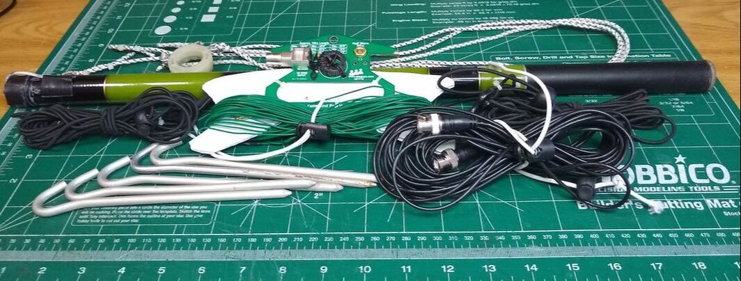
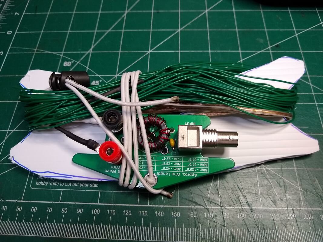
The antenna system consists of a 40-10 EFHW (~60' Wire matched to a QRPGuys EFHW transformer mounted on a DIY wire winder cut from a yard sign), 5 aluminum tent pegs, 2 pieces of shock or bungee cord for tying off the antenna ends, a 25' BNC terminated RG-174 coax, and a 14-1/2 ft fiberglass fishing pole with DIY collar and guy lines.
Total weight is slightly less than 1.5 lbs and it all packs easily. No adjustments needed for 40 or 20 and other harmonically related bands and internal tuner will handle 30, 17 and other bands just fine. I set it up as an inverted vee.
It's quick and easy to set up and take down and seems to just work!
2020-04-07 A few days ago I assembled another QRPGuys EFHW transformer kit which I had purchased by mistake a year or so ago. I like the one I've been using here at the house as an inverted vee that I don't want to take it down to use portable. In fact I like it better than the MFJ one I purchased. So this one will primarily be for portable. Testing it out just now with my NanoVNA I've made a few observations about installation.
First, a couple changes I made in building this one. Instead of using the wing nut supplied with the kit or a banana jack binding post as I did on the first one, I soldered a couple banana bullet jacks onto the board. I had to cut the ground trace on on the back of the board where I soldered the antenna connector so it would be isolated from ground. To mount the ground one I simply soldered it directly to the ground trace. For both i had to scratch off the paint and tin the surface. I think it turned out quite well. To attache both the antenna and ground I simply plug in the banana bullet plug. I used a 4 ft piece of 18 gauge speaker wire with an alligator clip on the end for the ground wire. The radiator I tested it with is the small antenna wire from Sotabeams. Cut for 40 meters, It is 58' 11" from the banana plug to the tip.
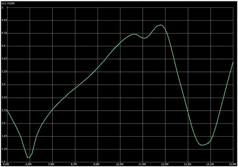
Now for the observations. First, I used the antenna wire from my original one to do the testing. The resonant frequency was just a bit lower on this transformer, interestingly. I also discovered that if I lower the center support about three feet there is a noticeable decrease in resonant frequency and increase in SWR. Probably not enough to actually be a problem but interesting.
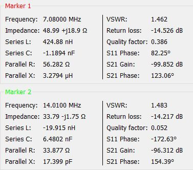
My next observation has to do with using or not using a ground wire. For this test I have an 8 ft dedicated ground rod immediately below the window sill where the feed point is located. The feedline from my rig and NanoVNA is about four feet of RG-58. The ground pig tail is four feet long and just reaches the ground rod. The two photos of my NanoVNA below show the difference. The first one (jut two SWR dips) is with the ground. The second one (with three dips is without the ground. It seems clear that a ground is the better approach.
This QRPGuys based EFHW is a very good antenna for either portable or permanent installation as long as you honor its 20 watt power limitation. I've had my first one up all through the Wisconsin winter supported by my 24 ft carbon fiber fishing pole without any problems. For portable it seems to me it is easier to set up and use than a dipole inverted vee with similar performance.
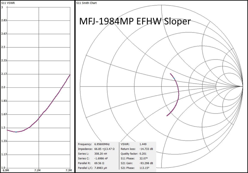
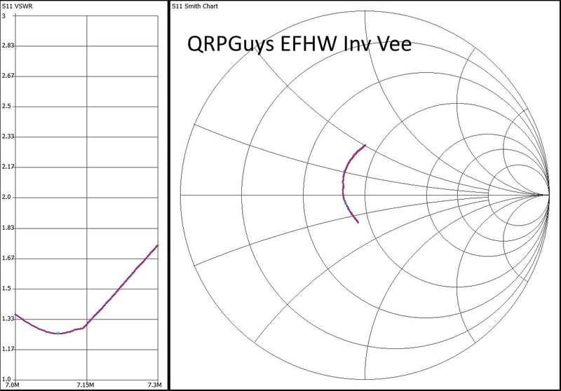
2019-12-19 Following are some potentially helpful graphs and data of my two EFHW antennas taken from the NanoVNA-Save software.
|
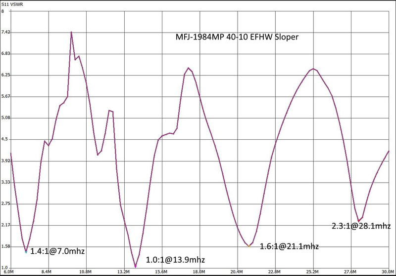
2019-12-17 Since getting my NanoVNA I've been "testing" every antenna I own, for fun and to become familiar with the NanoVNA. So of course I had to measure my two End Fed Half Wave Antennas, the one based on the QRPGuys 40-10 antenna set up as an inverted vee and the MFJ-1984MP that is set up as a sloper. As the graphs show, both are fairly well tuned. Of course I knew that as I use them all the time and both work very well.
|
2019-12-06 I've got a bunch of "portable" antennas. A Sotabeams link inverted vee with links for 17, 20, 30 & 40 meters. A Sotabeams trap inverted vee trapped for 17, 20, 30 & 40 meters. A QRPGuys based "random" wire end fed with 29 and 35 ft elements. A QRPGuys based EFHW inverted vee cut for 40 and covering 40, 20 and 15 meters without a tuner. Wolf River Coils TIA 1000 with the mini coil as well. A home brew 1 meter loop that is tunable on 40, 30 and 20 meters. What to do!?
Today I played with the random wire end fed, EFHW inverted vee and the trap inverted vee. Had contacts with all three. Performance of the trap and EFHW seem very similar (They were strung up identically using the same center support and end tie off points. The 29 foot sloper which was oriented the same way seems nearly the same on 20 and 30 meters but less effective on 40 meters. It, of course requires a tuner on all bands whereas neither the trap nor EFHW inverted vees need one.
Tentative conclusion: Unless space dictated the shorter length I'd not choose the 29 ft one. And between the trap and EFHW I'd choose the EFHW as it is simpler to put up and feed. also, in most installations it would require less coax feedline.
In fact, based on just a few days of using them I'm having trouble thinking a center fed half wave dipole or inverted vee (even a trapped or fan version or fed with open wire feed line) is the better choice over and EFHW even in a "permanent" installation. I'm using one I bought now as my main antenna. For years I used a G5RV exclusively and was very happy with it. I loved its multiband ability with a tuner, a clear advantage over a coax fed half wave dipole. But I think the EFHW performs as well and again is much simpler to put up and feed. for today anyway, I'm sold on the EFHW antenna!
2019-11-17 I really like my QRPGuys No Tune End Fed Antenna. I've been using it as an inverted vee running north and south for a couple weeks now along with my MFJ 40-10, 300 watt end fed half wave which is set up as a sloper, running east and west. I like being able to switch between them quickly and then using whichever one seems best for each QSO. They have nearly identical SWR bandwidths and patters on both 40 and twenty requiring no tuner. Their performance is so close it is hard to tell which one I'm using. If I had to say one was better, it would probably be the QRPGuys one as an inverted vee. I've thought of switching configurations just see if that makes any noticeable performance difference.
|
Yesterday evening. after having multiple QSOs with both I suddenly noticed the SWR on my QRPGuys one was all over the place while the MFJ was steady. That was still true this morning. It had been a windy rainy late afternoon so I suspected water was the culprit. So this morning, after a quick check of the feed-line coax using a dummy load, I disconnected the QRPGuys transformer and brought it inside. I had to leave just then but noticed everything was pretty wet. When I got back late this morning it had dried out so I did quick check with a 2700 ohm resistor. SWR was flat 1:1 across both bands.
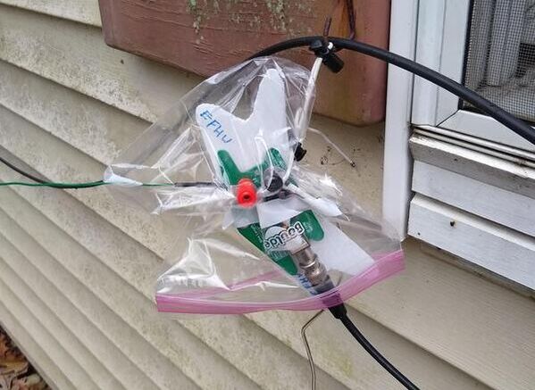
It occurred to me that one quart freezer bag would be the perfect size to fit over the transformer. So I cut a small opening at one corner for the radiating element to pass through, put the transformer inside with the feedline and ground wire going out the bottom and suspended it to the hook in my window shutter with a short small piece of shock cord. The SWR has never been better and it should stay dry now.
|
2019-07-31 After using only DIY wire antennas for some time (albeit most based on ununs and transformers I bought) I ordered an MFJ 40-10, 300 watt end fed half wave that came this afternoon. I couldn't wait so I hastily put it up. My rationale was that since I took down my G5RV I don't have any antenna that can handle more than 5 or 10 watts. I like QRP but it is fun to crank the power up now and then too. This antenna will handle the 100w capability of my IC-7100. I seldom run more than about 25 watts with it, but the option is there. Here's my installation.
The center (approximately) is supported by my Shakespear Wonderpole and the far end is tied off to the neighbors fence about four feet above the ground with a piece of bungee cord to give a bit of flex to the whole thing. I have a 30ft piece of RG8x coax running to my rig. In the last half hour I've had QSOs with it, both on 20 meters. I think I may need to trim the radiator a bit as the resonant point is very low on both 40 and 20. That's not a bit problem as I mostly work CW but the SWR gets up to near 2.5:1 above about 14.2 mhz. It's not quite as stealthy as my DIY QRP ones but not bad at all as the wire is black. Also the wire is pretty flexible which makes it nice. Overall I'm very pleased with it.
|
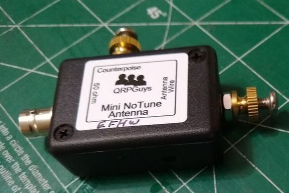
2019-07-28 Some weeks ago I purchased QRPGuys' Mini NoTune Antenna. It is a much smaller version of their No Tune End Fed Antenna which includes a wire winder. The circuits are identical and to all appearances the components are identical as well. I really had not had opportunity to check it out until today.
I installed the Mini No Tune Transformer in place of my Portable No Tune End Fed Half wave. The 59' 6" radiator, 3ft ground wire to a 8 in aluminum tent peg and 25ft RG-174 feedline are exactly the same. Nothing changed except the replacement of the transformer. On 40 meters the resonant frequency went from 6.9mhz to 7.4mhz. On 20 meters it went from 13.75mhz to 14.9mhz. Not sure what gives. More experimenting needed!
|
2019-07-22 Today I discovered that my x5105 internal tuner will actually tune the 40 meter end fed half wave antenna on 80 meters. I did manage one QSO with it but am not sure how well it actually performs. Might it do as well as something like a 29 ft end fed? If so that makes this antenna even more of a goto antenna.
2019-07-21 After putting up my 40 meter end fed half wave antenna discussed below and reading comments on Facebook about EFHW antennas I decided to do some testing. What I discovered is that it provides a good SWR without a tuner on 40, 20, 15 and 10 meters. With the tuner in my xiegu x5105 I can also use it on 30, 17, 12 and 6 meters. I don't have a lot of on-air results of how effective it is on all those bands but I have had 40 QSOs on 40 meters, 26 QSOs on 20 meters and two on 30 meters. I plan to stick with it for a while and continue to develop an opinion on how well it works as a primary station antenna.
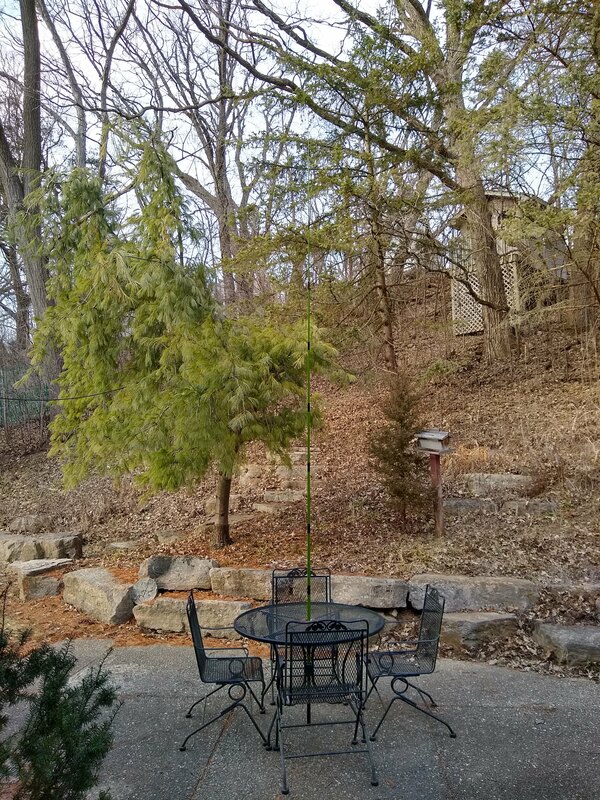
2019-03-27 The three pictures below show the two ends and center support mast of my EFHW 59 ft 40/20 meter inverted vee. The wire used for the radiator barely shows because it is so small, approximately 26ga or so. I use shock cord on both ends so everything has some flexibility. This evening I checked into the 4SQRP 40 meter CW net with it. The Net Control gave me a 449 and he was a 559 in here from 582 miles south west in Oklahoma. In addition I have made eight 5 watt QRP contacts in the last few days with it set up in a slightly different location. One of those was 1695 miles, SSB on 20 meters. The mast which is mounted through the patio table where the umbrella should be is 14-1/2 feet tall.
The antenna, including the 15 foot fiberglass push up mast works well, is very light and easy to put up, especially if you can stick the mast into the umbrella hole of a picnic table!
2019-03-22 One guy on Facebook suggested that the feed point for an EFHW should be really close to the ground, say a foot or so. So I moved mine down to about a foot. It appears that it lowers the resonant frequency noticeably but not enough to make much actual difference. Mine still has a barely measurable SWR across the entire 40 meter band. Next I am going to replace my mid point mast with a 14.5 foot one, dropping the peak by about six feet and see what difference that makes. The reason I want to test that is that my most convenient push up mast is 14.6' and collapses down to 22 inches whereas the 20 foot one only collapses to four feet. Obviously the shorter one is more convenient for portable use.
As nearly as I can tell with my measuring equipment the six foot lower apex doesn't make any difference at all. I suppose it might make an on-air difference but I'm guessing not. At least probably not enough that one could determine it in actual use. That's good for my purposes!
The 20 meter leg also has a less than 2:1 SWR on 12, 10 and 6 meters. How well it will radiate is yet to be seen, but it does not need a tuner. So the 40 meter length has very good SWR on 40 and usable on 20. That along with the 20 meter segment gives coverage of 40, 20, 12, 10 and 6 meters. Only 30 and 15 meters are left out! Not bad for a very simple antenna.
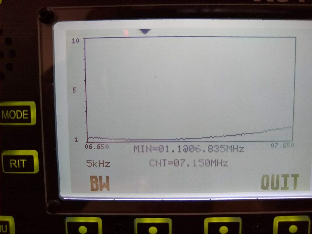
The "finalized" version is cut from SOTABEAMS light weight wire and is NOT broken at the 20 meter length but is one long wire, 59-1/2 ft long. SWR varies from 1:1 at the bottom of the 40 meter band to about 1:2 at the top. That is with a short ground wire to an aluminum tent stake in the ground. Without that ground wire the SWR rises to about 1.5:1 at the bottom of the band and over 2:1 at the top. It does resonate on the 20 meter band with an SWR of about 2:1 across the band.
As often happens not too long after finishing the "finalized" version of the antenna I answered a CQ by NC7H in Idaho, 1428 miles west! We were both 559. As usual I was using my x5105 at 5 watts. Not sure what he was using. That was on 14.060 on the 40 meter uncut inverted vee. SWR was about 1.5:1. I'm happy!
Here is the current, finalized configuration used for that QSO. The radiator is 59-1/2 feet long. Starts about 3 feet off the ground at the feed end. The apex is atop a push up fiberglass mast 14'6" high and the far end is roughly 3 feet up. I haven't cut it for 20 meters yet (and may not do so as 40 and 20 are the bread-n-butter bands for me). It measures less than 1.5:1 SWR across 40 meters. On 20 meters SWR measures about 1.5 to 1.2:1, highest at the bottom of the band. I found that using a short ground wire to an aluminum tent peg in the ground immediately beneath the 49:1 balun helps the SWR.
2019-03-21a I spent most of the afternoon playing with my end fed half wave antenna. The first part of that was trimming both segments of the antenna to resonance in their respective bands, 7.052 on 40 and somehow I failed to write down the 20 meter segment frequency! Then I tried the full 40 meter length on 20 meters. It works nicely. In spite of the fact that it's 20 meter resonant frequency is 14.5mhz the SWR is below 1.5:1 across the band.
After trimming there was a 1:1 SWR with or without a ground wire to a short ground stake. With just the 20 meter portion I noticed a very slight increase in resonant frequency without the ground but 1:1 SWR in both cases. It is erected as an inverted vee with the Apex near the center and 20 ft up. The 40 meter version does also works on 20 with about 1.3:1 SWR. It's resonant frequency is at about 14.5mhz and 7.05 on 40 meters. But it works nicely on both bands. Worked WA (1700 miles) on 20 using the full 40 m length, USB with 5 watts this afternoon and MT (1300miles) this evening on 40 CW.
2019-03-21 Late yesterday evening, just before dark I added the 34' extension to my 20 meter EFHW wire. Actually had a nice, solid % watt QRP QSO with 579 reports both ways with KB4MNG in NC on 40 meters with it. But it rained and the SWR went crazy so that ended my experimentation or the night. But today I put everything up again and did some tests.
The two photos below show the result of a short ground wire tied off of the transformer. As they show the resonant frequency is shifted higher by the addition of the ground. The ground I used was a 4 foot piece of wire clipped to a 7 inch aluminum tent stake at the foot of the 3 ft post supporting the transformer.
2019-03-20a After the successful deployment of the 20 meter end fed half wave antenna today I've decided to work on an extension for 40 meters. Since the element is currently 28' 10" long, I need to add another 34' 6" feet to it.
|
2019-03-20 Today is the first day of Spring but it sure doesn't feel or look like it. No sunshine and about 43 degrees! Oh well, still nice enough to get outside and play with my QRPGuys No Tune End Fed Half Wave Antenna. The radiating element is 28ft 10in long. I set it up both as an inverted L and as a sloper. Twenty meters is up and down so it's hard to say much about how they compare for operating. But I did notice one important difference. The resonant frequency is quite a bit lower in the sloper configuration than as an inverted L. I'm not sure I trust the center frequency reported on my x5105 graphs of the two but the graphs themselves are pretty close and tell the story. The difference is enough to require one to be alert when setting them up and using them.
|
In both configurations the connection point and the QRPGuys transformer was three feet off the ground. The corner of the L on the inverted L was 15ft up and the tip was a about a foot higher. In the Sloper configuration the far or tip end of the radiator was about 15ft up and the feed point at three ft. The feedline was a ten foot section of RG-174 for both of them. The connections inside the house were also identical.
With the inverted L configuration just before lunch I had a short 5 watt SSB QSO on 14.252 with N4WQB in Merritt Island, FL, 1072 miles. He gave me a 42 report and was 58 in here. He was running a linear but I don't know his power out. After lunch using the sloper I had a short 5 watt SSB QSO on 14.300 with KK5QT in TX, 1052 miles. He gave me a 55 report and was 59 in here. Again I don't know his power setting. But both configurations work. I didn't notice any hand capacitance or RF in the shack.
2019-03-18 Today I discovered that the ground has thawed deep enough to push a tent stake into it. So I set up one of my push up masts and strung up the QRPGuys No Tune End Fed Half Wave Antenna with the 20 meter element I had been playing with discussed below. To my amazement its resonant frequency was very low, about 13 mhz! After shortening it I got it up into the lower end of the 20 meter band. But compared with my G5RV it seemed to do very poorly. I also noticed some RF getting into my shack. I played around with feedline lengths and added a counterpoise. Neither gave me satisfactory results. Not sure what is going on with that!
I then put up my 35 foot end fed antenna. It seemed to tune up just fine on all bands but again, compared with my G5RV was unimpressive! So I then went with my four band trap inverted vee. It seemed to work a little better but the resonant frequency of the 30 meter segment is way too high. Again not too sure what is happening as the SWR looks quite a bit different from the last time I played with it. I was getting tired of antennas so kind of gave up for the day. It's possible I have the ends quite a bit higher than previously. So tomorrow I'll experiment with that.
2019-03-13 Before pursuing adding a linked extension for 30 meters to my 20 meter end fed wire I decided to do a bit more testing. Primarily I wanted to decide whether the length I have the 20 meter portion is what I want. To make that decision I probably need to play with different angles of the wire or how high the far end is above the ground. So I strung the antenna up inside (outside is a bit rainy today). The driven end was about three feet off the floor and the far end about seven feet. It ran through a very open part of the house so no walls or other things were closer than about five feet or so. The floor is above a four foot crawl space so the wire is at least seven feet from any actual ground.
The SWR, resonant frequency and usable bandwidth was very similar to the test yesterday outside. But what I did notice was considerable impact from hand capacitance. The RG-174 coax from the transformer to the radio was about four feet long. I played around with some short counterpoise wires to see how that would change things. They did change the resonant frequency and some lengths pretty much did away with the hand capacitance. Then I tried a 25 foot feedline without any counterpoise and the hand capacitance was gone! At that point I ran out of time and I'm not sure I trust those observations. I think I need to do more testing, probably with a more typical installation. Antenna experimentation never ends!
|
2019-03-12 The temperature rose to about 45 today with nice, bright sunshine! What a day. So I took my newly completed 49:1 end fed half wave antenna transformer from QRPGuys outside and strung a 28+ foot #24 speaker wire from the transformer to the peak of my garage. It was a hastily done thing so not very impressive but according to my x5105 the SWR was near 1:1 across much of the 20 meter band. I failed to take a photo of the SWR graph.
The band had several SSB QSOs and a few CW ones. QSB was fairly heavy. The maritime mobile net control operator on 14.300 in Houston, TX was very strong but he was busy rag chewing with a bunch of guys and never gave opportunity for me to even call. I think he could have heard me since he was peaking at nearly S9. It's frustrating when a net control doesn't provide many opportunities for check-ins.
But I'm happy that the antenna looked to the radio exactly as I hoped. Weather permitting I will keep playing with it and eventually experiment with a linked version covering at least 40 and 20 and probably 30 meters too. I may use connectors rather than aligator chips and forms between the sections of the radiator. We'll see.
|
|
2019-03-11 Today, the package containing the QRPGuys No Tune End Fed Half Wave Antenna transformer kit arrived. After dinner I'll get to work on it. And equally encouraging, the weather seems to have made a change. They are predicting at or near sixty degrees on Thursday! That feels like it's been a long time coming!
|
At left is my completed QRPGuys No Tune End Fed Half Wave Antenna transformer. It took about an hour to build. Haven't had opportunity to check it out yet. Perhaps tomorrow.
|
2019-03-01 While waiting for my QRPGuys No Tune End Fed Half Wave Antenna transformer kit I decided to cut a 20 meter element. According to their information it should be 28.8' or 28' 10" long. I'll cut a piece 29' long to give me a few inches to play with. I will use inexpensive 24 gauge RCA speaker wire for the initial tests. Then if all works out well, I'll cut more permanent pieces from the small gauge wire from Sotabeams. All this to help pass the time while the snow doesn't melt!
|
2019-02-28 I'm assuming that someday it will once again be warm(ish) outside here in southeast Wisconsin. With that assumption in mind I keep thinking about setting up outdoors and playing radio. Of course antennas is the major focus of that thinking. I've been watching a number of YouTube videos while I'm on the treadmill in the early morning and end fed antennas make up a larger percentage of the antenna types guys use for POTA (Parks on the Air), SOTA (Summits on the Air) and other outdoor portable activities. And of those, the end fed half wave is one of the favorites. So the QRPGuys No Tune End Fed Half Wave Antenna has been capturing my attention for a while. It's such a simple design that I'm almost embarrassed to think of buying rather than building one but on the other hand for it's low price it hardly makes sense NOT to buy it and save all the messing around involved in making one. (How's that for the logic of spending twenty bucks!) So last night I ordered one!
|
Part of what pushed me over the edge is the idea of combining that with the concept of a linked dipole which at least conceptually, provides a fairly easy way to change bands. Like the link dipole, simply lower the wire enough to reach a link and clip the leads together or separate them and bingo, you're on another band. And if you set it up in an inverted vee configuration it is as simple or simpler to deploy than a linked inverted vee. Simpler, actually, as you only have one link to mess with rather than two for a link inverted vee. One other advantage would seem to be the possibility of using a much shorter coax feedline than with an inverted vee, since it is fed at the end rather than at the middle. That also offsets one of the primary advantages of a random length end fed which can be used on multiple bands with a tuner. And theoretically, the EFHW doesn't need a tuner!
So on the surface it seems like it would have all the advantages of a full sized dipole over both the random wire or inverted vee antennas and none of their disadvantages. I'm anxious to get it built, have a nice day and give it a whirl. I'll probably start with one link allowing a 40/20 meter configuration set up as an inverted vee with one fiberglass push-up mast.
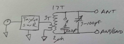 End Fed Half Wave Match with Tayloe SWR Bridge
The main issue one must deal with to use an end fed half wave antenna is the approximately 2000 ohm impedance it presents to the rig at resonance. One really simple approach is to use a transformer with the antenna connected to the parallel tuned secondary and the transmitter connected to the untuned primary shown at right.
I found a great, practical web site on the subject by M0UKD that I highly recommend. After putting a hay-wired version together on my bench I spent several hours experimenting and had a nice 559 QSO with another QRP station (I was running about 4 watts) in Pennsylvania. The antenna went from my shack's window sill about 4 ft above ground out to a tree reaching about ten feet at the far end. I didn't even have a counterpoise on it. I later did some checking of resonant frequency and impedance of the half wave wire itself using a short counterpoise. Initial results were encouraging and 20 meters seems to be very manageable.
I found a great, practical web site on the subject by M0UKD that I highly recommend. After putting a hay-wired version together on my bench I spent several hours experimenting and had a nice 559 QSO with another QRP station (I was running about 4 watts) in Pennsylvania. The antenna went from my shack's window sill about 4 ft above ground out to a tree reaching about ten feet at the far end. I didn't even have a counterpoise on it. I later did some checking of resonant frequency and impedance of the half wave wire itself using a short counterpoise. Initial results were encouraging and 20 meters seems to be very manageable.
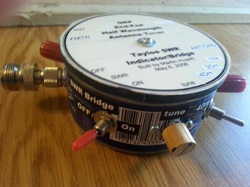 Completed end fed half wave matchbox in a tuna tin.
Several years ago I played with end fed half wave antennas and built such a "tuner." It worked but I was never fully convinced that I had done an adequate job of testing it out and the SWR was not great. So I decided to disassemble that one and be a bit more systematic in my approach, and try again. My goal was to build it into the tuna can I used before. It just looks cute! My first one included a Tayloe SWR Indicator/Bridge then offered by QRP Kits (link below) and I wanted to include it in the new one.
The finished product is shown at right. Using a 2200 ohm resistor as the load which reasonably well simulates the impedance at the end of a half wave antenna at resonance I measured less than 1.5:1 SWR on both 40 and 20 meters as indicated by my Z11 Pro ii tuner in bypass.
The finished product is shown at right. Using a 2200 ohm resistor as the load which reasonably well simulates the impedance at the end of a half wave antenna at resonance I measured less than 1.5:1 SWR on both 40 and 20 meters as indicated by my Z11 Pro ii tuner in bypass.
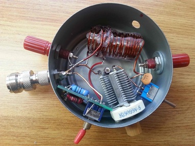
The photo at left shows the inside of the completed tuner. The transformer at the top of the photo consists of a 3 turn primary and 17 turn secondary (see schematic above). Both windings are air core wound on a pill bottle, about 3/4 inch diameter and 1 3/4 inches long. After winding I used a hot glue gun to run four beads of glue along its length, roughly evenly spaced around the coil and then removed it from the bottle. I wound and glued the 17 turn secondary first and then when it was cool added the 3 turn primary and glued it.
As the schematic shows the primary and secondary are not electrically connected. The ANT/GND connector on the right is floating, not connected either to the can or to the primary ground on the coax input connector. Some articles suggest a switch to allow the ground end of the secondary to be connected to the primary and coax ground providing a "counterpoise" from the coax, rig, etc.. I did not include or experiment with that.
As the schematic shows the primary and secondary are not electrically connected. The ANT/GND connector on the right is floating, not connected either to the can or to the primary ground on the coax input connector. Some articles suggest a switch to allow the ground end of the secondary to be connected to the primary and coax ground providing a "counterpoise" from the coax, rig, etc.. I did not include or experiment with that.
www.qrpkits.com/swrind_case.html The XMTR terminal on the left is a coax connector. The center pin goes to the xmt input pad on the Tayloe SWR bridge circuit board. The ant pad on the bridge circuit board goes to one end of the three turn transformer primary. If you don't want to include an SWR indicator as part of the matchbox then simply connect the center pin of the coax connector directly to the "hot" end of the 3 turn primary winding. The ground end of the primary winding, along with the ground pad on the Tayloe SWR bridge circuit board (if included) are connected to the coax connector ground which makes physical and electrical connection to the tuna can. So the tuna can itself is connected to the coax shield coming from the transmitter.
I mounted the transformer to the bottom of the tuna with two layers of double sided foam tape. That keeps it about 1/8th inch off the tuna can bottom but rigidly in place. The switch to connect the 220 pf capacitor shown in the schematic for 40 meters is a simple SPDT toggle switch. I connected the wiper to the ANT (hot) end of the secondary with the capacitor soldered from one switch contact terminal to the ANT/GND end of the secondary winding. I used a SPDT switch just in case in the future I want to add a second capacitor for another band. A SPST would suffice for just 20 and 40 meters.
The schematic of the completed matchbox is shown at the top of this page. The secondary winding consists of 17 turns of #16 enamel wire with a 3/4 in. outside diameter and about 1.74 inches long. It measures about 2 uh. The primary is three turns of the same #16 wire. Both coils are held in place by strips of hot glue, a technique I discovered some time ago which is easy and effective, if not beautiful! The variable capacitor is an old one from my junk box with a range of about 7 to 100 pf. To resonate the secondary on the 40 meter band I switch a 220 pf capacitor across the variable capacitor.
Does it work?!
Well "everything works" to some degree or other! Just after completing construction I turned on my FT-817 to listen on 40 meters. Many strong stations were calling CQ SKCC so I gave it a go with the power set at 5 watts. A very strong station back east heard me but couldn't copy my whole call. Then one in Illinois, only about 35 miles away called. He gave me a 559 report! I switched to the G5RV and tried the eastern station again with no response. Then using my IC-7000 and G5RV and 25 watts he gave me a 579. I think two things were in play. 1) the end fed half wave is only about ten feet above ground so is essentially a NVIS antenna giving a very short range. 2) the band wasn't great. I normally run around 25 watts for my CW QSOs, only increasing power when absolutely necessary. If propagation is there I get through, if not.... So not a conclusive test but interesting. I need to try getting the end fed half wave a bit more vertical and see how that works.
The next night I tried responding to a variety of stations on 40 meters who were calling CQ as part of the North American CW QRP Club Sprint. It was fun to hear the band so full of CW. I managed to snag one QSO with a station 134 miles away using 5 watts. No one else even knew I was in the world. His signal was very strong and he gave me a 599 (not sure if that was real or just the "normal" contest report), but compared with more distant stations, there wasn't much difference in the received signal level on the half wave compared with any of my other antennas.
Here are notes on a few more QSOs with it.
4/15/15 Had another 40 meter QSO this morning with a station over in Michigan approximately 250 miles away. Started out well. He was running 75 watts I was running 5 watts. He initially gave me a 569 but that quickly faded to where we had to quit as he couldn't copy me. I was still copying him at about 559 when we signed. I switched to my G5RV but he couldn't copy me on that either so I think 5 watts was just not enough power for conditions.
4/27/15 10:15 am Just had an SSB QSO with N9AER, control operator for Midcars using my FT817nd at 5 watts, powered by a 2200 mAH LIPO airplane battery and the end-fed half wave antenna and matchbox described above. Distance was about 150 miles. He was coming in S8 to S9 and gave me about an S5 report. Propagation seemed pretty good overall as I was hearing nearly everyone checking in very well, even the mobiles. This is making me think again about taking the FT817 on the upcoming backpacking trip even though the package would way about four pounds including the antenna.
4/27/15 11:25 am Had another SSB QSO via Midcars with W9MOE up in NW Wisconsin, about 300 miles. He was S8 and gave me about a 51 report. Have to say this is encouraging.
5/2/15 9:00 pm Just had a qso with KD8TUR using the FT817 and the End Fed Half wave. Lasted about 15 minutes. He is about 330 miles south East in Ohio. He gave me a 589 and he was a solid 599 here in Wisconsin. Toward the end signals were dropping but he still got my SKCC number just before we signed! I had the radio on internal battery and the voltage was showing right at 10v. Clearly if propagation is right this setup works. But that is not news. Probably could have used my dummy load tonight! I want to sling a rope up high in a tree in the yard and get the far end up in the air and see how it works. right now the far end is probably no more than 15 feet above the fed end and it follows the slope of the hill in the back yard so is really only about six feet off the ground of the hill itself. I nearly hung myself on it this afternoon mowing the yard!
5/9/15 Using my 33 ft. end fed half wave wire tied to my Tuna Tunah II I worked several stations in the SKCC Weekend Sprint (WES) this afternoon between 4:00 and 5:00pm, all using my FT817nd on internal battery. The furthest station was W7GVE which QRZ shows is just under 1500 miles. I switched back and forth between the Tuna Tuna II and my homebrew half wave matchbox and though I couldn't do immediate comparisons I couldn't tell any difference on receive between the two and both gave a 1:1 or at least very low SWR as indicated by both LED indicators on both tuners and on the FT817. The antenna as currently configured goes from the window (about 4' above ground) up into a pine tree with the tip probably about 20' up.
5/11/15 Tonight, again using the end fed half wave and Tuna Tunah II I worked Three more stations at five watts. VE2PID in eastern Canada on 20 meter CW gave me a 579, N5PAB on SSB in Mountain Home, Arkansas gave me a 53 and and W2IRK in Tennessee gave me a 56, also on SSB. I want to put the 51 ft wire on the tuner now and try that for several days. I'm feeling much better about the prospects of this type of setup, given the QSOs I had with it over the past week.
In Conclusion: Overall I am happy with the results of my matchbox and matching half wave wires. It is a simple and effective approach to driving end fed half wave wire antennas. The positive things about it are that it is relatively simple to build if you have access to a good variable capacitor and some wire. The biggest negative is that it is essentially single band. By that I mean you cannot use a 40 meter version on any other band as the whole principle is that at resonance an end fed wire looks like a resistance of approximately 2000 ohms which a parallel tuned circuit can quite easily cope with. If you want to work multiple bands you will need multiple wires cut to a half wavelength of the band and parallel LC transformer that will resonate at the desire frequency.
