Cheap Field Strength Meter
An inherent weakness of a digital reading Field Strength Meter is that in the real world the strength of a signal doesn't tend to be a Fixed number. You can't hold the meter absolutely still and even a small movement of it will result in a different reading. If you are tuning an antenna then by definition it is changing. The digital readout is therefore jumping all over the place and the result is somewhat useless. So though novel and fun to build, my own experience is that the digital approach described below is more frustrating than useful, in my situation at least. In my experience some things are just "analogue" and are more easily displayed with a meter movement which due to its inertia and averaging effect tells you at a glance what I am most often wanting to know. The peak or dip is visibly obvious on an analogue meter when it is illusive on a digital one. Field strength is one of those things.
A simple Stand-alone Analogue Field Strength Meter
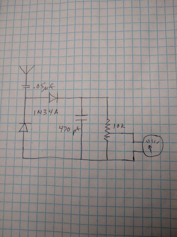
2019-11-20 The past couple of days I've gotten a renewed interest in my Signal Strength Meter (FSM) thanks to playing with my magnetic loop antenna again. In the course of doing that I posted some comments on Facebook about how I found using the FSM helped tune the magnetic loop. Several people made comments referring me to other's implementation of the FSM. Most of those include a potentiometer in the circuit. So this evening I decided to add one to my FSM and see how it affected it. Clearly it allows you to adjust the meter reading to deal with stronger or weaker signals but it seems that it also actually makes the meter more sensitive. That doesn't make a lot of sense to me. At the same time, perhaps the 10K pot across the 470pf capacitor actually makes the average voltage across the capacitor more "steady" passing a purer DC to the meter? Not sure but it seems to work quite well and I have to keep the wiper much closer to "ground" than I expected to control the deflection. regardless, it is a clear improvement to the design.
|
2019-05-20 This past Friday through Monday my friend, KD9KHI and I went to the Hamvention in Xenia, Ohio. What an experience. I told my wife, "I don't ever want to see another piece of radio junk in my life!" We walked almost all of the flea market and most of the vendor booths and attended a couple forums. It was a lot of fun and we bought just a little stuff while there, nothing over $50.
|
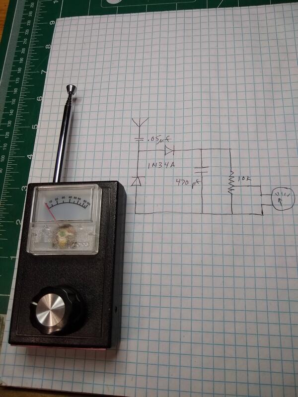
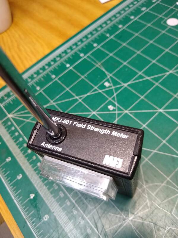
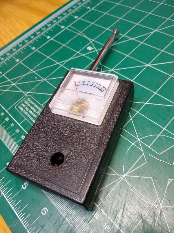
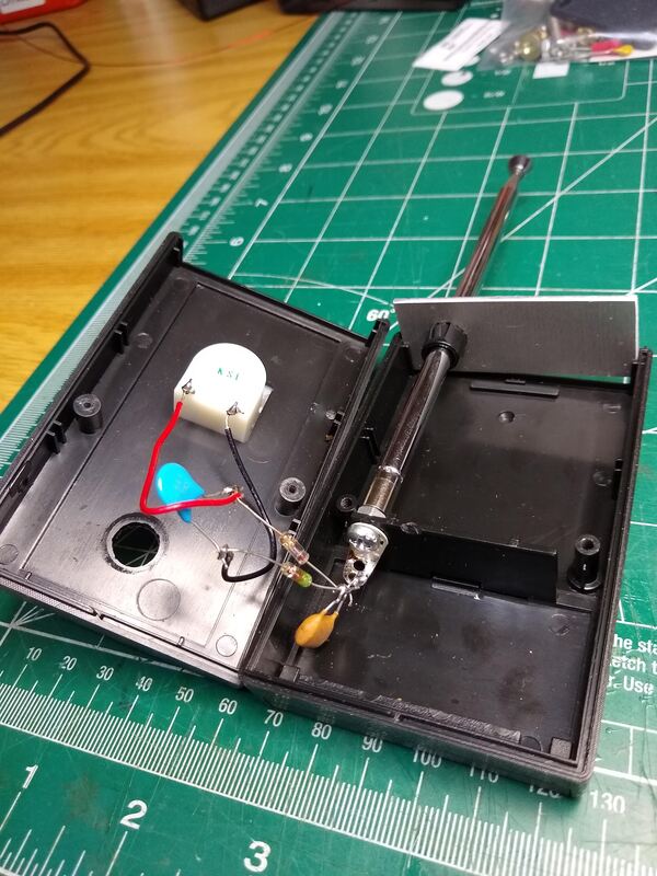
One of the things I bought, for $6, was what I thought was an MFJ-801 field strength meter. Turns out it was significantly modified and at least from my perspective, useless. BUT the case, antenna and meter were intact so I stripped it of its modified guts and added my own version!
|
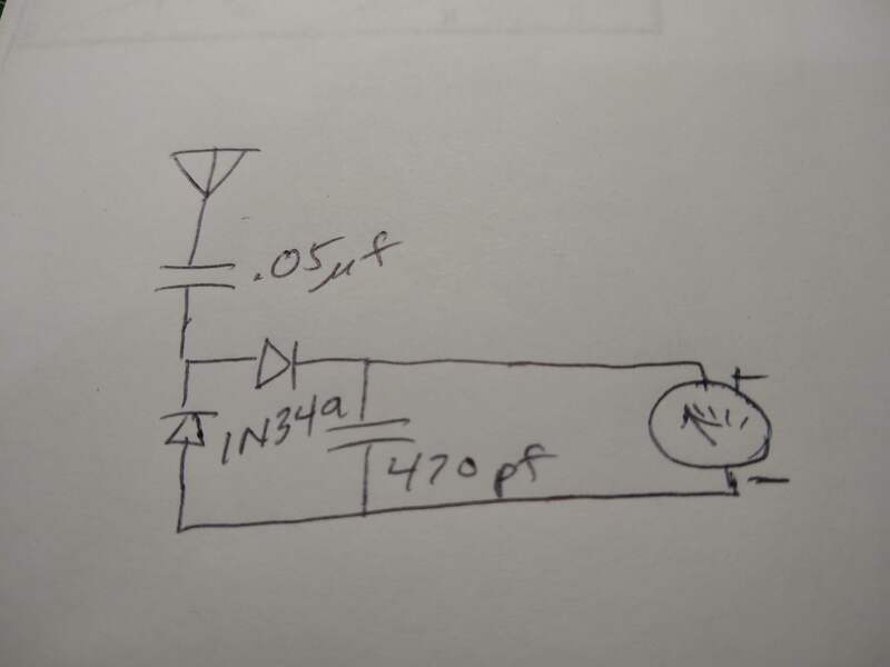
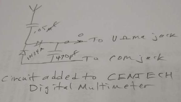
The circuit, shown at right, is about as simple as one can imagine. It's identical to the one I used for the digital multimeter version described below only with the output from the full wave rectifier going to the analogue meter rather than to the digital multimeter. Capacitor values are approximate and not critical. But the diodes are critical. The germanium 1N34a, from crystal set days, provide good sensitivity.
|
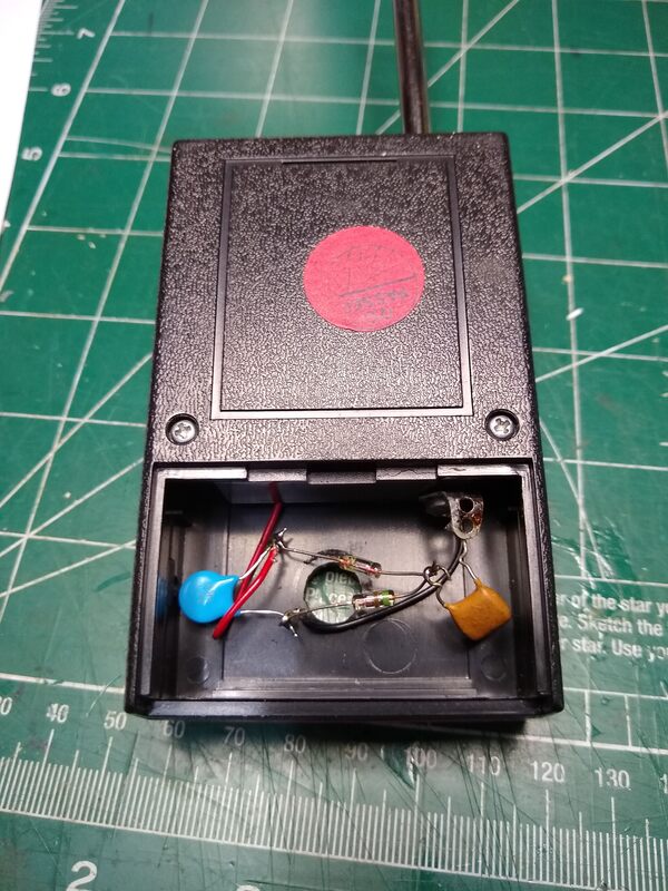
Schematic and construction of my modified MFJ-801 Field Strength Meter.
|
I'm not sure they are 1N34a's but they are germanium and work! My construction technique isn't the most beautiful but works too. I simply soldered the various components together in "free space" rather than doing some sort of circuit board.
My first use of this "new" gadget was to set it across the room from my magnetic loop and be impressed with the signal strength peak when the loop is resonant! And the dip when I rotate the antenna broadside to the meter was distinct. That was nearly impossible to do with the digital version described below as the "numbers" on the display constantly and rapidly fluctuate. I'm happy with this super simple gadget! I think it will prove to be a useful tool.
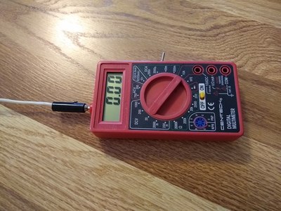
Adding Field Strength Measurements to a Digital Multimeter
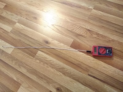
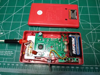
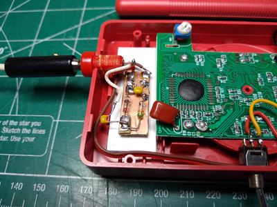
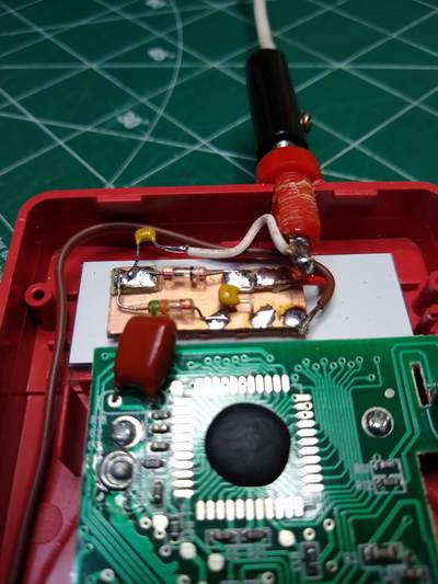
Below are photos of my build of the Field Strength Meter described in the YouTube video by K7AGE. I chose the "Manhattan" style to build it, gluing little tiny pc board pieces onto a larger piece to form the junctions of the various devices. His YouTube is based on an article by KB3VZL in the February 2015 QST (page 71).
|
At first I didn't think I needed the switch but then realized that to use the meter as a voltmeter I'd need to protect the diodes so added the switch.
I mounted the small pc board with a tiny piece of 3M double sided foam tape. The banana jack is cemented into the hole i drilled with super glue as is the switch (since I couldn't find a matching nut!).
My antenna is simply a 24 inch piece of #14 electrical wire.
|
Does it work? Well, it does register voltage on the meter when I key my transmitter and the closer it is to the antenna the larger the reading. So, yes. Will it be useful? Time will tell. A practical matter is that I need a way to key my transmitter located inside while I wonder around the yard or neighborhood to seek what it reads key-down! I'll check back when I solve this "ground level" testing problem and actually try to use it!
Assuming it works, what will useful information will I actually know as a result? Perhaps just that I was able to make it in a half hour or so! That in itself is an accomplishment and reduced my junk box contents just a tiny bit! :-)
