Comparing 40/20 Meter Fan Inverted Vee and 40/20 Meter Trapped Inverted Vee
On-Air Comparison
2018-06-27 This past weekend my friend Gary (KD9HKI) and I (K0BXB) did Field Day at the flying field of our local RC Plane Flying Club. Gary used the 40/20 meter Fan Style Inverted Vee and I used the 40/20 meter Trap Style Inverted Vee. He worked PSK-31 using about 25 watts and I worked mostly CW but four with SSB, using 5 watts. He logged 40 contacts and I logged 32 contacts. Most of his were on 20 meters and most of mine were in 40 meters. He had a manual tuner but said it required very little adjustment. I did not have a tuner but still was able to work all across the band. My FT-817nd reduced its power a little in the phone portion of the 20 meter band due to the increased SWR but I still made one SSB contact there.
Conclusion
We had no other antennas to compare with on-site, but my conclusion is that these antennas work well and are comparable with each other. Given how comparable their test specs are (see below) and their on-air performance I'd generally choose the trap style version simply because it is somewhat easier to set up given it only has two legs. That is, if I were operating QRP. The Pico Traps, according to the SOTABEAMS website are limited to ten watts. They do have versions for up to 100 watts.
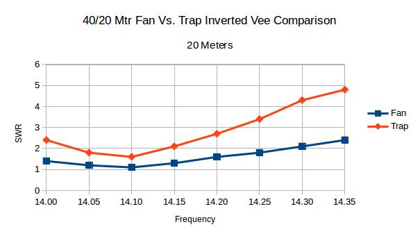
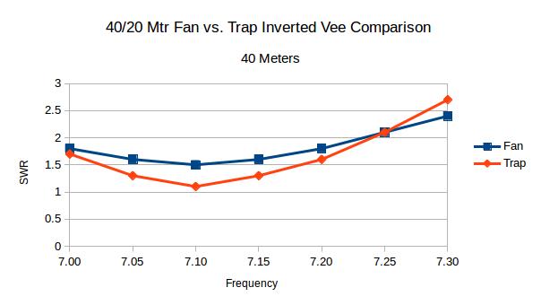
SWR Comparison
2018-06-8 This SWR comparison is based on my own experimentation with a home brew 40/20 meter Fan Style Inverted Vee and a home brew 40/20 meter Trap Style Inverted Vee. I built them as similar as I could given what was at hand. My primary motivation is to have an antenna for Field Day June 23-24. I want the entire QRP station to be lightweight, simple to transport and deploy and not be dependent on trees. My tests in the back yard have convinced me that either antenna will work.
The center insulator/connector for both antennas was mounted 16-1/2 feet above ground atop a Shakespeare TSP20 Six-Piece Wonderpole with the top section removed. The feed line for both was 25 feet of RG-174 coax. An MFJ Model MFJ-259B HF/VHF SWR Analyzer was used for all measurements.
The 20 meter legs of the fan inverted vee are each 16 ft. 8 in. long. For the trap antenna, the 20 meter portion from the center insulator to the trap was 15 ft. 5 in. The additional 40 meter extension from the trap to the end was 14 ft. 5 in. Total leg length is 29 ft. 9 in.
|
The 40 meter legs of the fan dipole are each 31 ft, 3 in. long. The 40 meter legs for the trap inverted vee are each 29 ft. 9 in. which included both the 20 meter length of 15 ft. 5 in. and the 40 meter extension of 14 ft. 5 in.
|
Observations
For some reason the bandwidth of the 20 meter trap antenna is a bit less than for the fan antenna. Further, the SWR curve is a bit flatter for the fan antenna on both bands.
With only two legs to deal with the trap version is simpler to deploy than the fan version which has four legs.
The trap version seemed to involve more fiddling around to get it right than the fan version. That may be just me and how I approached each than an actual fact!
I found the Pico Traps from SOTABEAMS easy to build but less easy to actually attach the antenna wire. The holes provided in the small PC board on which they are built are too small for most wire one might use. Also, getting the wire lengths right involves considerable adding and taking away wire and I don't think the small plated holes and traces would last long when doing that. So I actually fabricated some loops of solid copper wire to which I then attached the actual antenna wire.
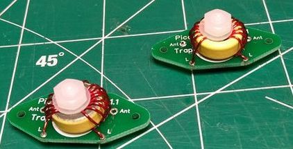
Assembled Pico Trap
|
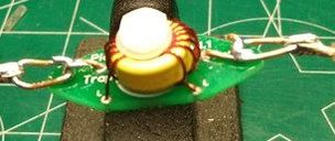
Pico Trap with my wire loops for attaching to the antenna element.
|
The way to assemble and tune a trap antenna seems to be to first do the shorter legs, 20 meter elements in this case, without the traps or next band (40 meter) extensions attached. When you have the shorter elements tuned the way you want them, add the traps and extension and tune the longer elements. You will have to go back and change the shorter elements some but that will be relatively little and you'll get a good overall result. As everyone warns, it will take some fiddling around!
I really like the Shakespeare TSP20 Six-Piece Wonderpole for the center support. It is light weight and easy to erect and take down. I removed the top section which reduces it's height from 20 ft. to about 16-1/2 ft. I found a small rubber grommet that fit snuggly on the tip of the remaining section which I embedded in the little PC board center insulator I made and so makes it really easy to attach the antenna.
I was concerned about rain. The center insulator on both antennas is very exposed and the BNC coax connector is facing upward so water will likely run right into it and cause a problem. Further the top end of the mast is open to collect water too. So I fabricated from clear plastic sheet a cover for it. It is held in place by tie wraps on each leg of the antenna. For the trap version I did something similar to cover the traps.
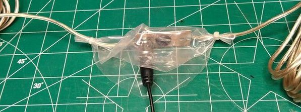
Plastic cover for center insulator. Functions sort of like a rain poncho!
|
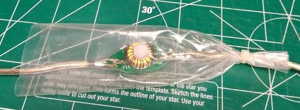
Plastic cover for traps. Only the top end is closed so it can block water running down the antenna.
|
Finally, having access to an antenna analyzer really helps with the whole process. Thankfully my neighbor Jerry N9AC loaned me his MFJ-259B. I would likely have given up without that. Using my FT-817nd and my MFJ-204B would have worked but would have taken a lot longer. The MFJ-259B allowed me to fairly quickly determine the antenna SWR across the entire band and make corrections accordingly. The MFJ-204B will show you the resonant frequency and give a reasonable indication of the SWR at that point and that is about all. I'm somewhat of a computer nut also and used LibreOffice Calc to record and plot my readings.