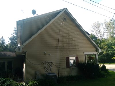
SOTABEAMS Link Inverted Vee, modified
|
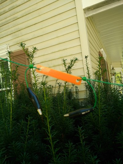
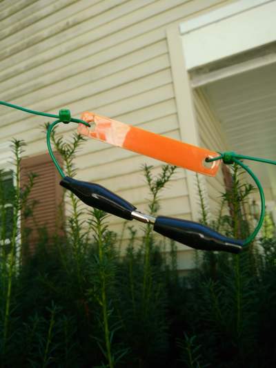
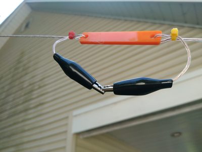
In a nutshell: The link dipole is a dipole cut for the highest frequency desired with extensions added on for the subsequently lower frequency bands. These add sections are separated from the other sections with short insulators which are then either "jumped" or left isolated by using alligator clips. A little trimming of the length of each segment may be required to bring it to the desired resonance point within each band. Keep in mind that each segment closer to the center insulator impacts the overall length so there may be some back and forth required to get it exactly where you want it. It's two main advantages over other options such as a trapped or fan dipole are better bandwidth on each band and each antenna is a full half wave antenna, not impacted by either traps or other radiating elements. It's main disadvantage is that to change bands requires lowering the antenna and physically clipping or un-clipping the alligator clips as needed.
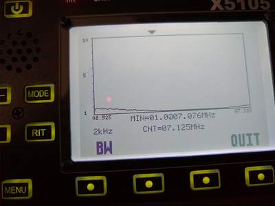
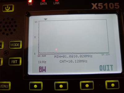
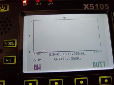
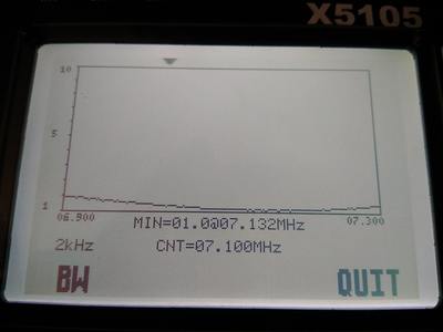
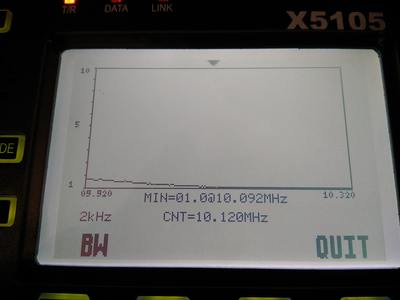
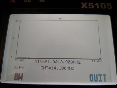
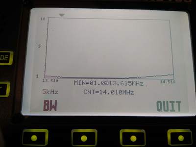
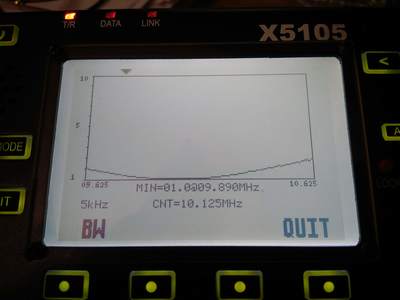
2020-04-02 Today is one of those rare "perfect" days. At 9:30am it is 43 degrees and bright sun in a very clear blue sky! Thank you, Lord! So, I did a thorough test of this link inverted vee as I left it last evening. Here are the results:
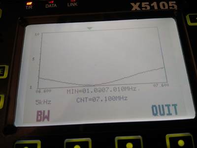
- 40 meters. Resonant @ 7.151mhz, 1.76:1 @ 7.0mhz, 1.54:1 @ 7.3mhz
- 30 meters. Resonant @ 10.076mhz, 1.07:1 @ 10.1mhz, 1.18:1 @ 10.150mhz
- 20 meters. Resonant @14.01mhz, 1.05:1 @ 14.0mhz, 1.58:1 @ 14.350mhz
2020-04-01 After tuning my wire vertical yesterday, I decided to take it down and put up my link inverted vee based on the Sotabeams Link kit. Of course, after putting it up and checking it with my nanovna I had to make come changes! That's the problem with having test equipment! No antenna is or ever will be perfect. But one is always tempted to try to fix it's imperfections. So I spent way too much time today messing with this things. I ended up making two changes: removing the 17 meter link and replacing it with a six inch extension in both legs. The result? It now has lowest SWR of 1.1:1 at 7.108 with a 1.5:1 SWR at 7.0 mhz and 1.7:1 SWR at 7.3mhz. I ran out of time to check 30 and 20 meters but I'm expecting it to be within both bands.... I hope!
|
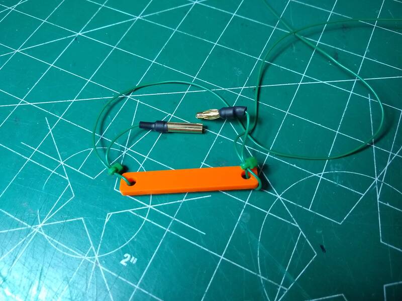
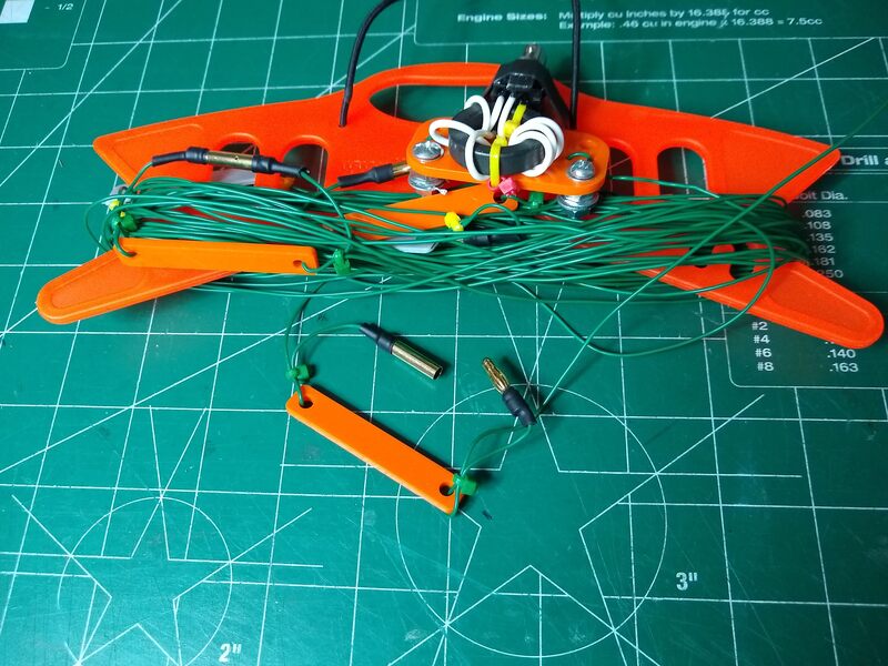
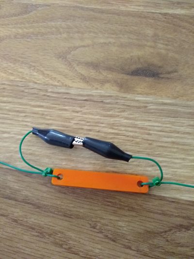
2020-02-13 A couple days ago it occurred to me that replacing the bulky alligator clips on this ling inverted vee with bullet banana connectors would make a much neater package. So today I did that. I haven't had opportunity to use it on-air with these connectors but I think it will be at least as easy as the alligator clips. It certainly does wind up better.
|
2019-12-21 I'm in a reflective mood this morning (barely sunup!) about antennas. And I've concluded that for a good and simple multi-band antenna, the Linked dipole or inverted vee is it! It's relatively easy to make and tune. Since it's a half wave dipole it performs very well. Almost anyone can make one from a wide variety of materials. It's only down side is that band changing requires physically clipping and/or unclipping segments. And that is a very simple thing to do in most cases. It doesn't require an antenna tuner. Just connect the coax to your radio and go! It has few if any power restrictions so is useful from QRP to max power (if your feedline can handle it). As an inverted vee it is very simple to set up.
When portable I recommend using small bungee cord or what in the camping/backpacking world is called shock cord and cord locks to tie the ends off to a tree or whatever. the main reason on I like that is that to change bands simple grab the lower end of the antenna, slide your hand to the link you want to connect or disconnect, do it and let it go! No need to lower the center support mast. Speaking of center support masts I've used several different carbon fiber and fiberglass push up fishing poles ranging in height from about 12 feet to 20 feet and all worked well. It helps if your antenna is made from very light, maybe #24 or #26 line such as small speaker wire to keep it light for the flimsier push up fishing poles. Some of the best wire I've found is the "small wire" from Sotabeams. It is strong and very light and doesn't tangle easily. They also sell a nice kit for building a linked dipole which is what I started with.
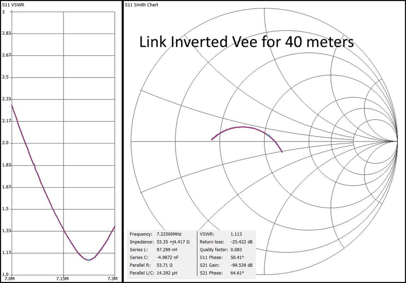
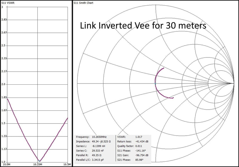
2019-12-19 When you get a new toy, you have to play with it! Well, I got a new toy. It's a NanoVNA antenna analyzer. I guess it can do a lot more than that, but that is all I've done with it since it came a few days ago. I've found two meaningful uses for it so far, both being SWR measurements. In one case, if you are dealing with multiband antennas like trapped dipoles and end fed half wave antennas designed to be used on multiple bands without any switching involved the NanoVNA allows you to show the SWR curve across the entire range the antenna is designed for. I've done that with two of my EFHW antennas as well as a trapped inverted vee. The other use I've found is looking at the SWR graph of a single band antenna as precisely as you want to do, which is what I've done today with this Linked Inverted Vee.
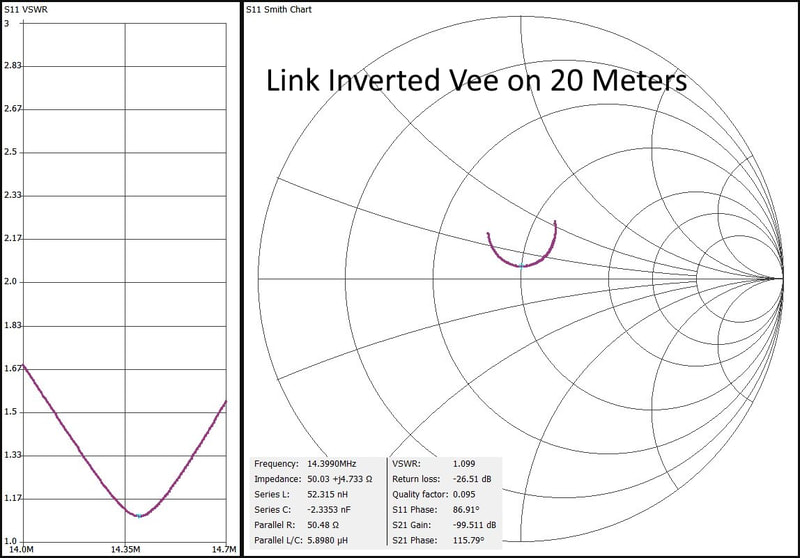
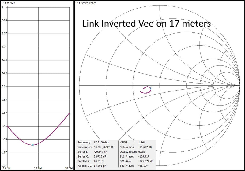
I've narrowed down to each of the four bands the inverted vee is designed for, 40, 30, 20 and 17 metes. The graphs below show the SWR curve, Smith Chart curve and the data at resonance for each band. It could use just a bit of adjustment in segment lengths but all are well within useable limits without a tuner across all four bands as is.
SWR Graphs and data for the four bands in my linked inverted vee.
After playing with my sloper and inverted vee EFHW antennas, trapped inverted vee, a 17' 20 meter vertical and now this linked inverted vee, I have the feeling that this is indeed a very good antenna. It provides a full sized dipole (or inverted vee in this case) for each of the bands. No fuss, no bother other than having to physically clip or unclip the appropriate segments for the band you want to use. Like the trapped inverted vee it is just a bit more complicated to put up than an EFHW but not appreciably so. It does require more coax feedline than an EFHW but no more than a trapped antenna. And band changing requires going out into the elements. But its "brute force simplicity" make it quite possibly at least the backup antenna that should always be in a portable package along with whatever you might use as your primary antenna.
|
One other observation I have is that the link inverted vee (and any "dipole" type antenna is just a tad bit quieter than my two EFHW antennas. The difference is unlikely to impact many QSOs but does feel slightly better to the ears.
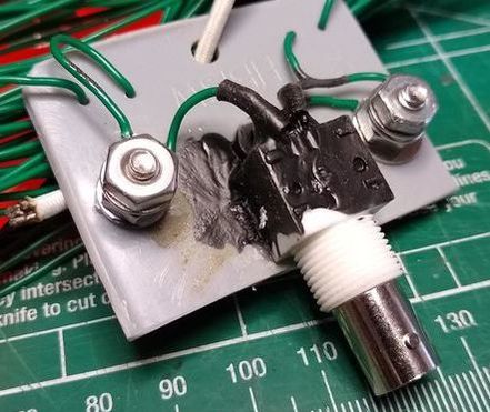
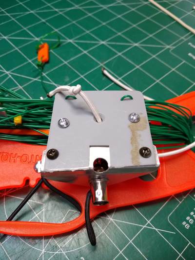
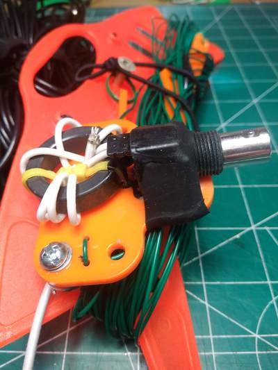
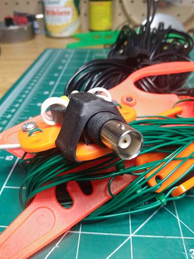
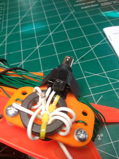
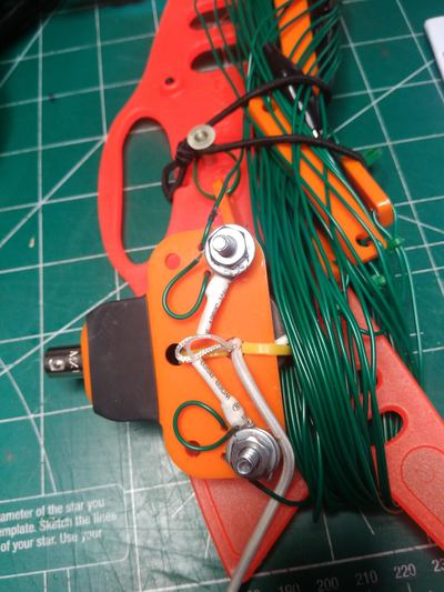
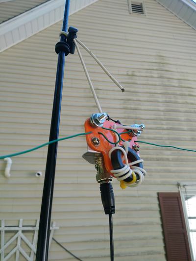
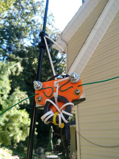
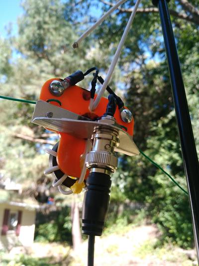
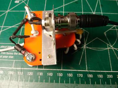
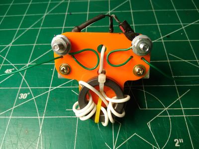
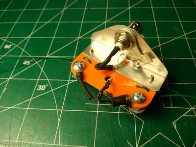
2018-11-13 Minor improvement of the center insulator. The aluminum bracket I used to mount the BNC connector on the center insulator for the feed line is clearly a "work of art" but it is also kind of large and makes packing the antenna into my little portable bag somewhat difficult. So a while back I ordered some surface mount BNC connectors on Amazon. They came yesterday so I used superglue to mount it to the "outlet cover" center insulator in place of my elegant aluminum bracket. The black gunk in the photo is Liquid Tape which I smeared on liberally to keep water out of the connector and secure the soldered leads. The little wires on the back of the BNC connector are quite small and fragile. I think the result is an improvement.I also replaced the screws with shorter ones to further reduce its overall size.
|
|
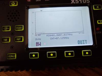
2018-10-27 The SWR readings are so flat across all the bands with this antenna that I've been concerned whether the 1:1 balun on the center insulator was "lossy" and causing the reading. So I made my own center insulator without the balun and moved the legs of the antenna to this new insulator. I just ran the SWR sweeps again with my x5105 and below are the results. They are only slightly, perhaps not any different from the ones with the balun. My conclusion is that at least from an SWR perspective, the balun has no impact. Whether it makes any other noticeable difference either in antenna performance or RFI in the shack I don't know.
|
The photo above shows the non-balun center insulator.
|
Modified 17, 20, 30 & 40 meter link inverted vee
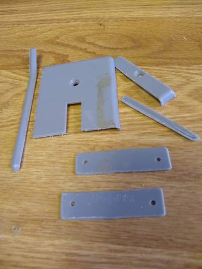
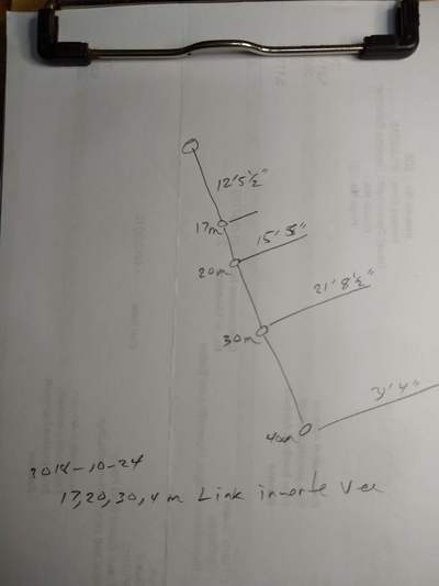
2018-10-24 As mentioned on my trap antenna page I'm beginning work on a four band trap inverted vee to cover 17, 20, 30 & 40 meters. The modification is the addition of 17 meters. As I planned that, it occurred to me that I could modify my original SOTAbeams three band link inverted vee by adding another insulator at the 11 foot point in the existing 20 meter leg. So I cut two insulators from an old electrical switch cover (this one seems to be made of pretty flexible, tough as opposed to brittle plastic), found a couple sets of small alligator clips and am setting to work! I used a calculator in an article which includes a calculator for dipoles and inverted vees online to calculate the segment length and it was right on!
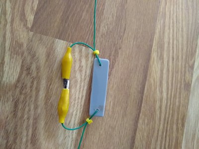
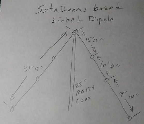
The insulators cut from the switch cover plate are on the left, the finished link is in the center and a Sotabeams version of a link at right. Theirs is prettier! The sketch shows the points from the center insulator where the links are inserted. Will mine work?!
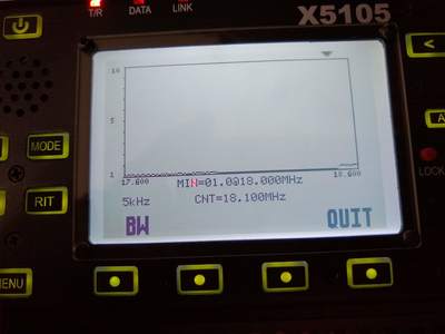
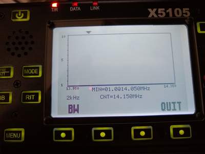
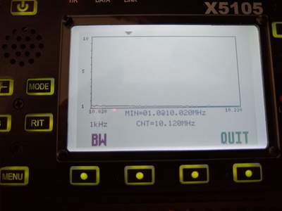
I couldn't wait so I put it together, took it outside and replaced the trap antenna with it and ran the SWR sweeps shown above. Whether it will work or not is yet to be seen, but the SWR sure won't prevent it's working!
Original 40 30 & 40 meter Link Dipole
2018-10-22 Proud as I was of the bracket I made (see below) to mount a female BNC jack on the center insulator of the Sotabeams Linked Dipole Kit, the result was a bit "bulky" and was hard to put into portable rig bag. Thinking about that for a while the thought came to me to try to mount a chassis mount BNC jack right onto the plastic center insulator. So I dug around in my junk box and found one I had removed from something. And after more than a bit of fiddling with location and how to mount it I came up with what is pictured in the photos below.
I should have taken some in-process pictures I guess, but sorry, didn't! The jack has a plastic body so I roughed up one side of it as well as the face of the plastic center insulator with some fine sand paper then used super glue to mount it. After letting that dry and attaching the coax I was still a bit unsure of it's permanency so got a piece of 1" heat shrink tubing and put it over the whole thing. I also smeared some of it with Liquid Tape just to add a bit of strength to the coax connections to the jack. I've only used it a couple times since but all seems secure and it is a bit lower profile than with my aluminum bracket. The coax hangs a bit straighter from the insulator as well. I checked the SWR bandwidth and made a few contacts to be sure I hadn't tampered with anything critical - which I had not.
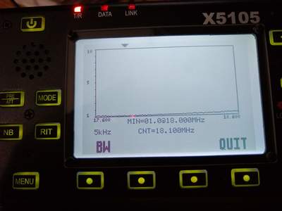
2018-09-27 As intended, I strung up the antenna this morning and tested the SWR on it. The results are in the shot of the x5105 SWR screen below for all three bands. I also verified them on my Icom IC7000 by checking the SWR at the extreme end of each band. By any measure they are impressive readings.
The pictures below show the details of the center insulator, the antenna segment links and the end termination. This is the setup used to take the SWR measurements above.
Conclusion? I think I'm finished fiddling with it. It seems like a very good three band portable antenna. It's advantages are good SWR bandwidth on each band and it provides a full length dipole for each band. Its one disadvantage is that it must be lowered to change bands. I found that much easier using the Shakespeare TSP20 Six-Piece Wonderpole than the 5.4 meter Bamboo Pattern 11 Section Telescoping Fishing Rod, though it only takes a minute or two with either one. Of course it could also be hung from a tree or other support as well, either as a dipole or an inverted vee.
|
2018-09-26 In case you hadn't noticed, I can't stop fiddling with my antennas! I did a bit more trimming of the 20 and 30 meter segments today to move the resonant frequency just a bit higher. Then I decided to replace the very fragile #24 RCA speaker wire with SotaBeams light weight antenna wire. I'll test it out tomorrow to make sure the lengths are correct with this new wire.
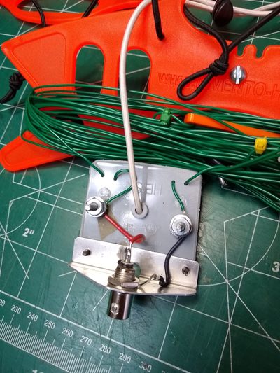
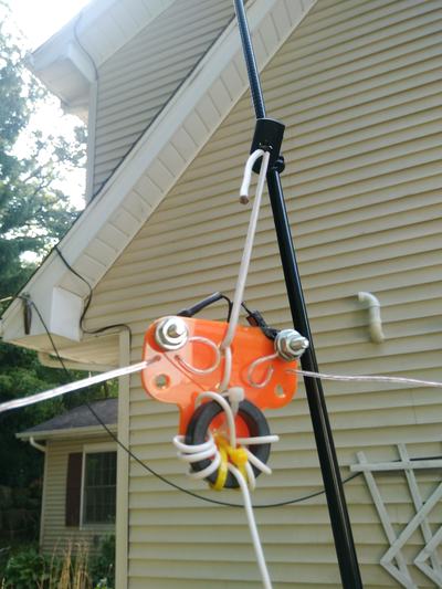
As the photos below show I have modified SotaBeams center insulator considerably. First, I drilled four small holes which in pairs form a strain relief system for the antenna wires. Second, I used screws, washers and nuts to connect the antenna to the coax. Third, I added a bracket I fabricated from scrap aluminum so I could mount a female BNC connector.
I checked the SWR after making those mods and nothing changed. It looks a bit less scrappy than my previous version which had the BNC connector dangling on a coax tale. it also hangs better on my fiberglass mast. And it is easy to attach and detach the 25 ft. coax feedline.
|
2018-09-25 10:45am Just checked into ECARS on 7.255mhz (SSB) using my X5105 and the just-erected link dipole. He was near Pittsburgh, PA, about 450 miles south east and running 900 watts. He was a S6 in here and gave me an S7! We both were amazed! So, I think I can say the antenna works!
The SWR was flickering around 2:1 but the radio didn't seem to care. I may trim all three elements a bit as they all tend to be toward the low end. I do need to play with the installation to see how that impacts it. Currently one end is about three feet above ground and the other is only about a foot off the ground. The center is around 17 feet.
2018-09-25 It's about 9:00am and I just finished hanging and testing my Linked Dipole Kit from Sotabeams, in spite of the hoards of mosquitoes! SWR results are shown in the photos below. I'm sure it could be tweaked a bit but it more than covers all three bands so I'm not messing with it further, especially with the mosquitoes like they are today!
Initial observations? Great antenna! So simple it is almost embarrassing. On my Shakespeare TSP20 Six-Piece Wonderpole it is really easy to put up. But more importantly, it is quick and easy to change bands. Each time I only had to lower the pole by one or two sections to reach the clips and add or remove a segment. But the broad bandwidth, very low SWR and hopefully full-sized effectiveness make it well worth the small trouble of lowering and clipping/unclipping. It is as easy to erect as my 40/20 trap dipole and much easier than the 40/20 fan dipole which has two separate elements that must be staked out. I'll use it for a few days and then may have additional observations. But for now, it's a winner!
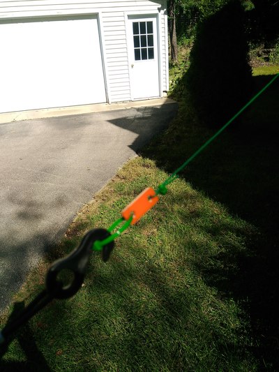
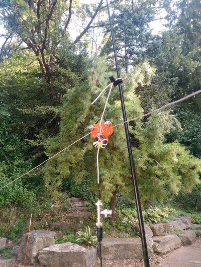
Below are some photos of the installation and antenna details. I like shock cord and cord locks. To tie the center insulator off to the mast I put a small grommet on the mast near the top and then using a cord lock made a tight loop in the shock cord that will not slip down over the grommet. It makes it simple and quick to hang and the shock cord provides some flexibility.
2018-09-24 A week or so ago I ordered a Linked Dipole Kit from Sotabeams. The kit contains pretty much everything you need except the wire and I have lots of that. So I built it using the small #24 RCA speaker wire I had on hand from other antennas I've been playing with. I began by winding the choke using some RG174 I have had for along time. It was pretty time consuming as it was really stiff and slick and hard to hold in place. Then came attaching a BNC connector. What I had was a crimp on one but it became obvious quickly that I don't have the tools to use it. But I did manage to solder it onto the coax and it appears to work.
I began with the 20 meter element. A link in the documentation for the kit provides a calculator so I went with its recommended lengths for the legs. Stringing it outside, SWR measurements verified that was pretty close. Tonight I cut and added the 30 meter and 40 meter extensions. I'll put it up tomorrow and test it out.
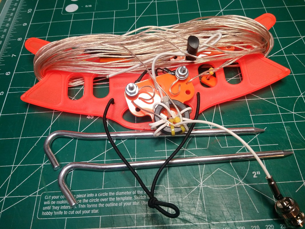
The concept of the linked dipole is really simple. It is essentially a dipole cut for the lowest frequency. That then is subsequently cut at appropriate lengths for each higher frequency band. A spacer is then inserted at each cut and alligator clips are used to add or remove each section so the remaining length is correct for the band chosen. The result is a resonant dipole for each band. The negative is that the band change is manual, requiring lowering the antenna enough to reach the alligator clips to connect or disconnect. But the positive is that you have a full length dipole for each band so efficiency is high.
