NanoVNA
|
2020-01-14 Why might you want a NanoVNA? Well, interesting question. I have to admit the primary reason I got two of them... is that they're pretty inexpensive and everyone is raging about them and all the wonderful things they will do for me. Kind of why I downloaded and play with PSK and other digital modes, bought my several ultra portable rigs, built a magnetic loop antenna, etc.. And a good part of that is what amateur radio is all about, exploring new things and ideas. So one doesn't need much justification, providing the bank account and time allow it without bankrupting the more important parts of one's life.
Being a bit less philosophical, what will a NanoVNA do or do more simply that I can't already do. I think the honest answer is that for most of us most of the time it won't do much that will have much impact on our ham radio life. On the other hand, if you are into experimenting with or building antennas it will potentially be of significant help.
|
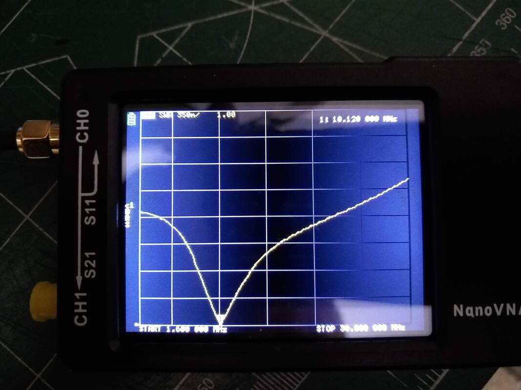
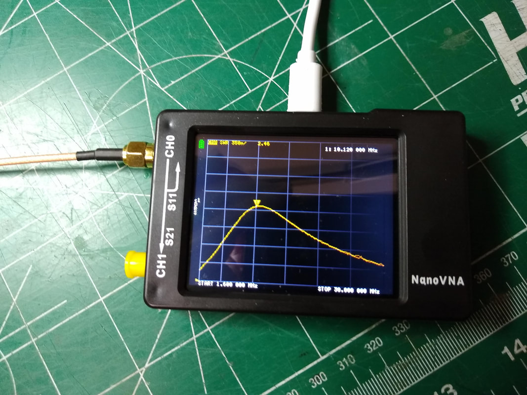
Scan of a 30 meter antenna using the NanoVNA showing the SWR is 1:1 at 10.120mhz.
|
I often think back to my ham radio beginnings. I had a one or two tube transmitter and a Hallicrafters S20R general coverage receiver with BFO that covered the ham bands. The antenna connectors on both consisted of a couple of screws about an inch apart where you could connect a piece of wire and a ground. And though I had just gotten my novice license, I knew nothing! I can't reconstruct in my memory how on earth I got them to work. But I did. The antenna I remember, was a folded dipole made from 300 ohm TV twin lead. I'm not sure how I determined how to make it but I did and made contacts with it on 80 and 40 meters. My TR switch was a big double pole double throw ceramic knife switch.
When I upgraded to a Heathkit DX-60 transmitter I switched to a dipole with a coax feedline. Can't remember much about that but again, it worked. I remember, probably from a QST article, getting details for and building a forward and reflected power meter. It didn't give SWR readings but at least showed you whether forward power was greater than backward power and for the first time I began getting at least a bit of information about my antenna. And then, like most others I got my first SWR meter or bridge which was all I had for many, many years to tell me anything about my antenna system. The idea was that the lower the SWR, the better the antenna! Even today I have a stand alone one that finds its way into various feedlines from time to time. Honestly, that is about all any of us really need. And since most radios today include that function we probably seldom really even need a stand alone one.
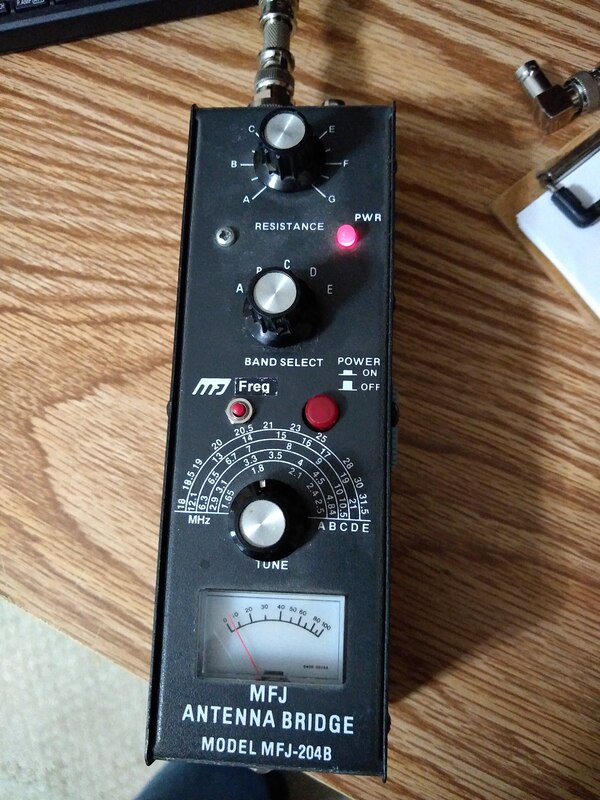
The MFJ-204B measuring the resonant frequency of a 40/20 meter trap inverted vee on 40 meters.
I have yet to actually own a real antenna analyzer but I've used a couple MFJ ones including a 259C model belonging to a friend. They are a quantum step up from the 204B antenna bridge and will tell you just about everything you can know about your antenna from the input side. Of course nothing connected to the feedline end can tell you how well or in what directions your antenna radiates. For that you need a field strength meter and potentially acres of property and lots of measurements. Or, like most of us, just use it and make up your own mind about its performance compared to others you use or have used. Even if you use only purchased, pre-built antennas, some kind of antenna analyzer is probably worth the investment.
|
The first standalone SWR gadget I owned was a Model MFJ-204B Antenna Bridge. I still have it and even occasionally use it. Covering 1.6mhz to about 32mhz, it allows measurement of the resonant frequency and the resistance at that resonant frequency. It isn't super accurate but you can learn a lot about an antenna you are building or using with it. Being portable it makes adjusting an antenna much easier than running in and out of the shack as you make minor changes to your antenna. If that is all you have, you can build and adjust antennas effectively. And you don't need much sophisticated technical knowledge to use it.
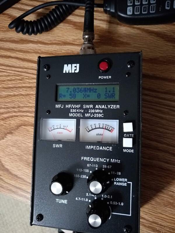
MFJ-259C Antenna Analyzer looking at a 40 meter inverted Vee antenna.
|
A limitation to most of the above, including many inexpensive SWR Analyzers, is that they only tell you the impedance and/or SWR of your antenna at a single frequency. To get a picture of that information over a band or segment of a band you have to take multiple measurements and plot them on a graph or something. From that you can then see how your antenna looks to your transmitter across the frequency range you care about. That is where some of the modern transceivers, better antenna analyzers and the NanoVNA begin to look more attractive when playing with antennas.
For me, the antenna light-of-understanding began to really brighten when I got my Xiegu x5105 QRP transceiver. It includes an SWR plot function that graphs the SWR of whatever is connected to its antenna terminal over a selectable frequency range between about 1.6mhz and 50mhz. With the push of a button you can look at the entire 40 meter band in a single plot and tell immediately where your antenna is resonant and its SWR across the band.
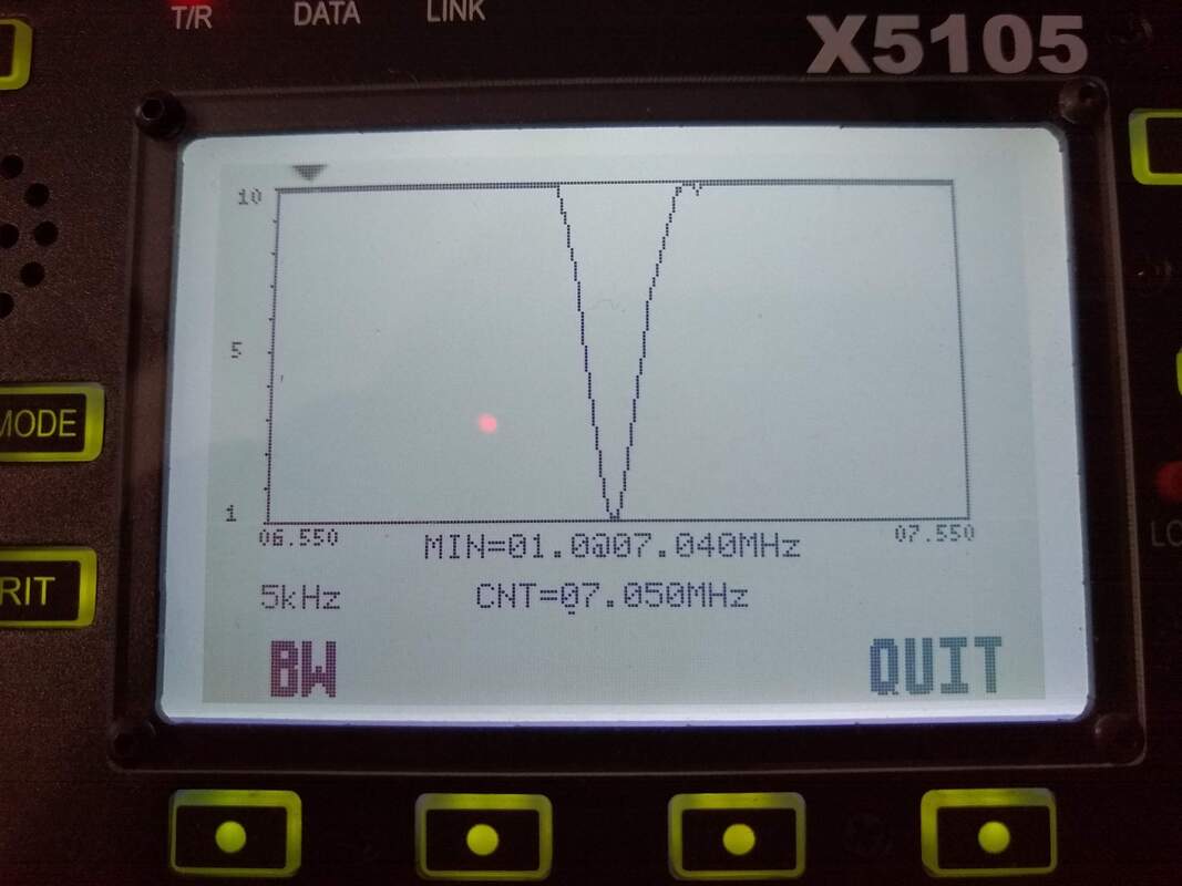
Magnetic Loop Scan across the entire 40 meter band on the Xiegu X5105.
Since x5105 isn't limited to the ham bands as it can sweep any segment range between 1.8mhz and 50mhz, its fairly easy to find and make adjustments to your antenna and see the results immediately, even if it falls outside the ham band. That is one of the weaknesses of the 204B. If your antenna doesn't resonate in or real close to a ham band, you are lost.
At the most basic level, the NanoVNA takes that SWR plot idea and allows you to sweep any range of frequencies between 50khz and about 900mhz. Now you can look at a multiband antenna on all its bands simultaneously or find that illusive resonant point of your antenna, wherever it is. THAT is helpful when building or adjusting an antenna.
A couple years ago having that capability would have saved me hours of checking SWR, running inside to plot it and repeating as I was trimming a fan dipole for 40 and 20 meters. When building a trap antenna, for example, with the NanoVNA you can see immediately how changing one segment impacts all the others. Or, when tuning a portable vertical like the Wolf River Coils TIA 1000 its easy to see whether you need to move the tap up or down and about how far, even if it is currently resonant between bands (which it always seems to be when first setting it up).
NanoVNA SWR plot of the MFJ-1984MP end fed half wave 40-10meter antenna across all frequencies from 6mhz to 40mhz.
It takes a bit more fiddling and understanding of the NanoVNA itself to use it but if you are willing to do that, it's a powerful, inexpensive antenna analyzer alone. I'm guessing that is how most of us will use it. And at $40 to $60 it pretty much matches or beats most of its competition as an antenna analyzer in both cost and function.
|
But it can offer a lot more than that for antenna tinkerers. When making a trap antenna, for example, measuring and adjusting the traps to the right frequency is no small task. There are many ways to do that but the NanoVNA probably does that about simplest as any. The first time I built a trap dipole I used a DIY solid state version of the old Grid Dip Meter. It worked okay. But to get an accurate frequency reading I had to attach a frequency counter or monitor it on my transceiver across the room. The NanoVNA will do that task fairly simply, once you understand it and have made up the "jigs" to attach your trap.
So, what's the real cost of a NanoVNA. Well at $40 to $60, not much cash wise. It's primary cost will be coming to grips with it. You don't have to understand everything about it and how it works but you do have to grapple with some fairly involved menus and settings, new terminology, small screen, SMA connectors, calibration, etc. And to go beyond just using it as a "sophisticated antenna analyzer" looking primarily at SWR, you'll need to begin to understand the Smith Chart and similarly complicated things. But for most of us analyzer uses we can ignore that and just look at the SWR curve. For just that, it's cheap. But for looking at SWR alone, a stand alone MFJ or other Antenna Analyzer will be much simpler to use and perhaps even more effective for you.
My bottom line? If you like to play with antennas, filters, etc., and like learning new things and playing with gadgets, get yourself a NanoVNA. If not, take your spouse out to dinner with the money and keep using the SWR feature on your radio!. The NanoVNA isn't essential, but it is fun!
|
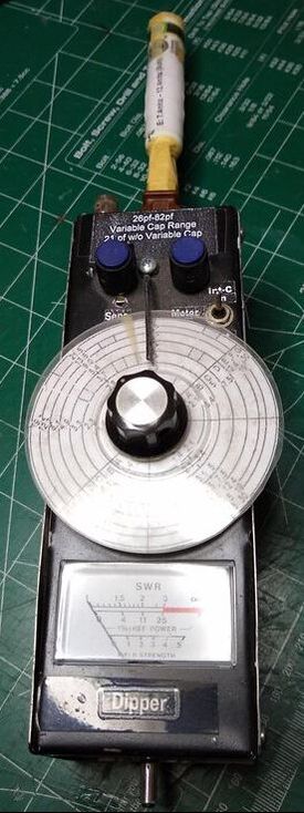
DIY Dipper used to tune traps on my first multiband trap dipole.
|
The paragraphs and pages below are my "lab notes" as I play with my NanoVNA. They are arranged in reverse order, the most recent at the top.
|
2019-12-30 I know a VNA can be used for much more than looking at the SWR of an antenna. But exactly how to use if for those other things is something I'll have to learn. Perhaps lesson 1 will be how to determine the resonant frequency of series and parallel circuits.
Why my interest in parallel and series resonant circuits? Antenna traps is the simple answer. I've built two trap antennas in my 60 plus years of ham radio. (That I remember, anyway!) The first was an attempt to make a two band end fed half wave antenna for 40 and 30 meters. I didn't know about the 49:1 transformer at the time so was using a tuned secondary transformer to drive it. I had it working fine on 40 meters so made a coaxial trap for 30. It worked, sorta.
|
Resources:
A guide to the NanoVNA, a book to alleviate the absence of a manual in the box. At the Kindle-Shop. (https://www.amazon.com/gp/product/B083BB82G5).
|
The second is still in use and is a trap dipole for 40, 30, 20 and 17 meters. I purchased the trap kits from Sotabeams. My biggest challenge was tuning the traps. I had a FET version of a grid dip meter and ended up with a pretty good job. But I've known since that there has to be a better way. Is a NanoVNA at least ANOTHER, if not THE other way?
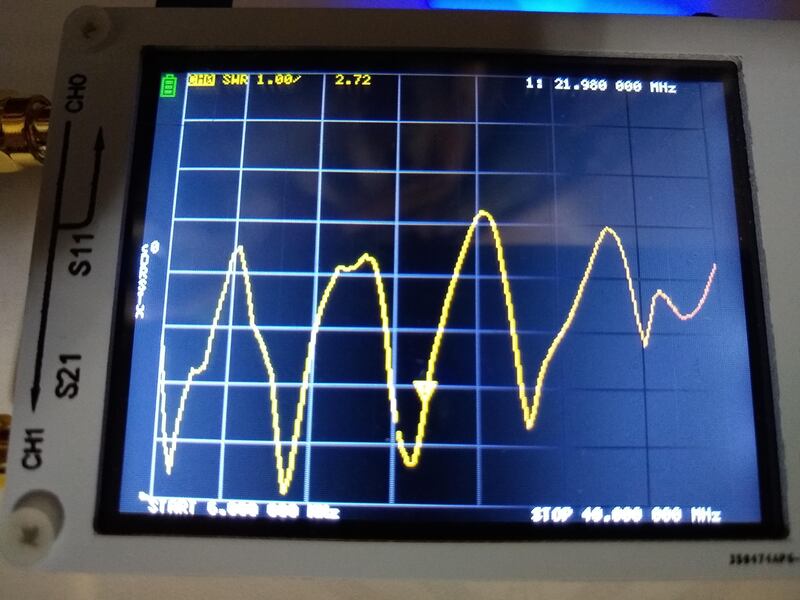
Testing a Series Resonant Circuit with the NanoVNA.
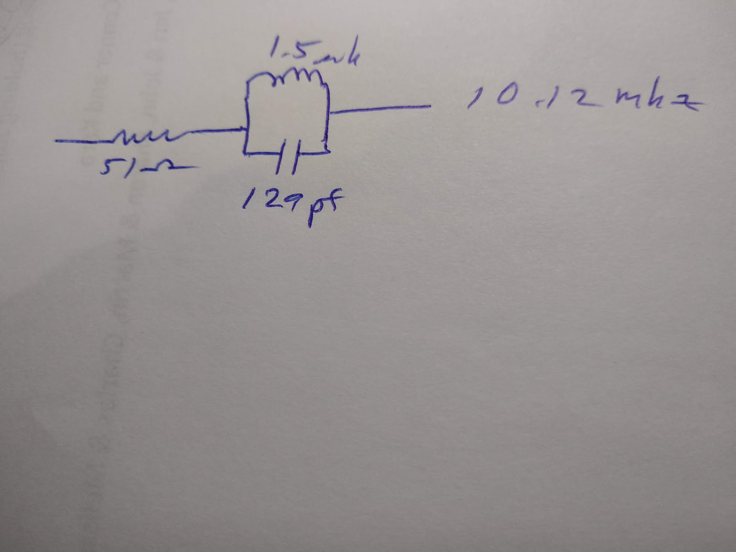
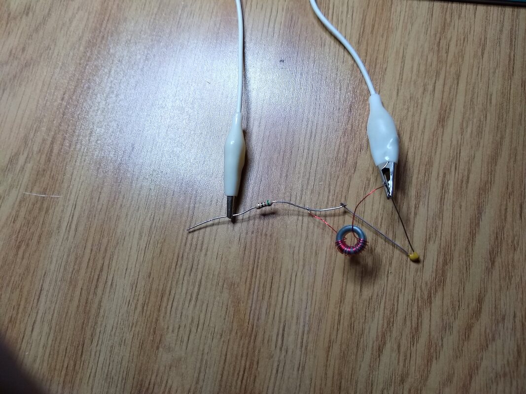
I started off by digging around in my junk box and coming up with a 1.5 uh toroid inducter from some old project, a 129 pf cap and a 51 ohm resistor. Then I rigged up a "test set" consisting of a pigtail with an SMA connector on one end, a BNC jack on the other and, a BNC to so239 adapter and a PL259 plug with pigtails and alligator clips. top get some sense of physical stability and integrity I taped the pigtails down so they won't move and calibrated the NanoVNA leaving the alligator clips separate for the open, shorting them together for the short and clipping them onto the 51 ohm resistor for load. Then I soldered all three in series. The test setup and schematic are shown above.
The results" a 1.0 SWR occurs at 10.12 mhz. As the Smith chart shows it crosses the 50 ohm line right in the center and the complex impedance reading is 50.3 ohms and 2.3 nH. Both the Smith chart and SWR curve are shown above in the photos. As you go up the Smith chart curve the inductance increases and as you go down it turns to capacitance and increases demonstrating that at resonance the two cancel each other out - which of course we all knew! Next I'll figure out how to make similar measurements with the inductor and capacitor in parallel.

Testing a Parallel Resonant Circuit with the NanoVNA.
To do the parallel resonance test I soldered the 129pf capacitor in parallel with the 1.5uh inductor and then the 51 ohm resistor in series with the pair. See the schematic above and the photo of the "test jig". I initially tried connecting the clip leads from the NanoVNA directly across the resonant circuit. But the resulting impedances are so high that the whole thing was off the scale of the NanoVNA. So I clipped one lead to the free end of the resistor and the other to the opposite side of the coil-capacitor pair. The photos of the SWR and smith charts on the NanoVNA show the results. Their is a clear SWR peak at resonance, limited by the resistor. the Smith chart is a bit less clear. The small yellow marker on the right vertical line is the resonant frequency point and since it is on the right limit means the impedance at resonance is infinite as you would expect of a parallel resonant circuit.
Looking at the Smith chart, increasing frequency is downward and decreasing frequency above resonance is upward. So the chart shows that as the frequency increases above resonance the parallel circuit looks more and more capacitive. As you decrease the frequency below resonance it appears more inductive. I think.... I need to consider that more before drawing too many conclusions. The one thing that is clear is that the parallel pair have their highest impedance at resonance and therefor are most effective in "cutting off" the length of wire added to the open end of the pair when used as a trap, which is what we want! It further explains why additional wire used to resonate on the lower frequency band will be somewhat loaded by the trap inductor and therefore shorter than would be the case for a true half wavelength dipole.
Comparing NanoVNA clone and Hugen NanoVNA-H units
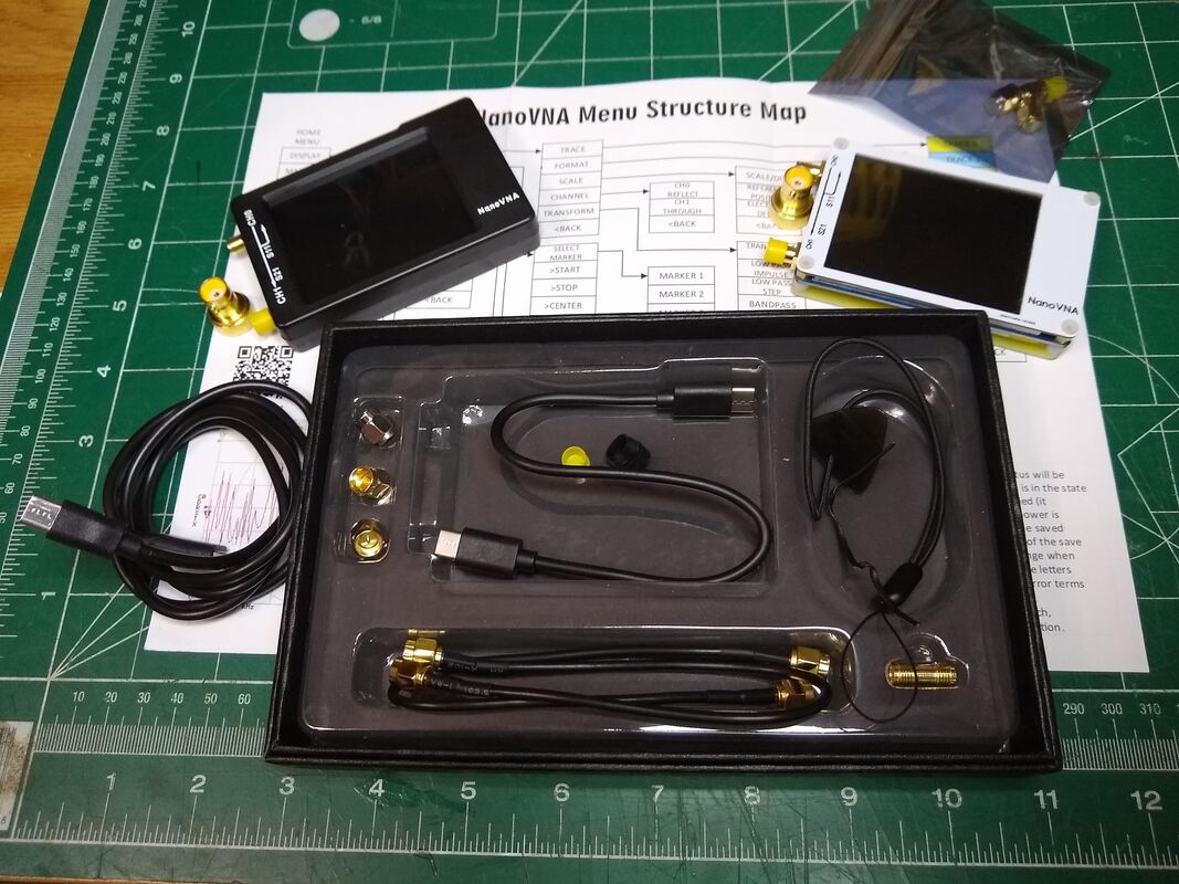
Hugen NanoVNA-H on the left (black) and Amazon Clone (white) on the right. The box and cables and menu sheet came with the Hugen. The clone came alone with just the calibration plugs.
2019-12-28 Shortly after buying a NanoVNA through Amazon 12 days ago I decided, whether necessary or not, to buy a "Hugen NanoVNA-H" via Alibaba. It arrived three days ago, about half the time it took to get the clone via Amazon. I made the decision after just a short time playing with the Clone and thinking I was having problems with the touch screen, etc.. Turns out most of my problems were not knowing what I was doing! It was a too-hasty decision. But never-the-less, I'm not unhappy in the end. The Hugen is hardware v3.3 and has a 450mAh battery.
Comparing the two devices functionally, I really can't see any difference of note. They work identically. All readings I've taken so far have reaveled no notable differences in SWR readings, frequency of resonance, etc.. The "units per vertical" setting of the display is a little different between them but not enough to be any sort of problem. And the measured SWR results, the only thing I have really used them for so far are very close to what I get using an MFJ-259C or the SWR sweep functions on both my xiegu x5105 and G90. So I judge the two units as "identical" functionally.
The main physical difference is that the Hugen came in an enclosure whereas the clone does not have one. So the clone is a bit more fragile and just a bit harder to handle. Otherwise the two units are identical physically. As to what came with them and packaging there is quite a difference. The clone came alone with just the three calibration plugs. No cables or adapters. No paperwork of any kind. The Hugen included a USB to USB C charging/connecting cable, a USB c-USBc cable, two extender cables a female to female adapter, carrying strap and the three calibration plugs. The Hugen also included a sheet showing the menu layout.
Packaging wise, the clone was in a small padded envelop inside a cardboard box and in a Amazon bubble envelop. The Hugen was in a small padded envelop, inside the box along with all the cables and connectors, then wrapped in bubble wrap inside a larger cardboard box and then in a DHL envelop. Both arrived in perfect physical and functional condition with one small exception. The USBc-USBc cable with the Hugen does not work with my phone with either the Hugen or the clone. A third party one I already had works fine with both.
|
2019-12-28a Today the case I ordered for my NanoVNA clone came. Took me a few minutes to figure out how to mount the VNA in it but I finally did.
The "blank" on the right side is actually a small storage compartment. It's shown with the calibration plugs and jack cover inside.
I think it is a functional enclosure and an improvement to the unit.
|
|
Doesn't seem very robust but adequate. Clearly makes the NanoVNA easier to handle and seems safer.
2019-12-18 Well, in spite of the fact that it was about 8 degrees outside, I decided to try to make practical use of the NanoVNA. Some weeks ago I decided to home-brew a wire 20 meter vertical. Using the SWR sweep feature on my Xiegu X5105, I found it very difficult to find the right length, not because the X5105 didn't function properly, it did. But it's sweep range is limited to about 10khz so if the antenna is outside that range it is hard to "find it" to make appropriate adjustments. But after playing with the NanoVNA it occurred to me that since you can set it to sweep a very wide frequency range it should be easier. So I set its sweep range to 6.5 to 30mhz. Then I put up the antenna (I already had a fiberglass push-up pole holding up my EFHW inverted vee), strung out three 33 ft' radials which came with my Wolf River Coils 1000TIA antenna. Then using a 3 foot coax I connected the NanoVNA and had a look.
The Wire vertical element was 14 ft long and the antenna resonated at about 16.5mhz. I lengthened it to about 18 feet and it resonated at about 13.5mhz. So I trimmed off a foot or so and checked again. It was 14.02mhz. The SWR was about 2.4:1 and I was cold so didn't look at the Smith chart to see what the resistive and reactive components were. But I did connect the feedline to the shack and right away had a QSO with NM1I, Butch in MA. He gave me a 549 and he was 569 in here. Unfortunately the band faded to nothing so we barely got the essentials across, But it works! Inside, at the end of my about 30ft coax its resonant frequency is about 12.1mhz with an SWR of 1.8:1. So the feedline is transforming the unmatched impedance at the antenna to something strange! I need to do some more testing to get a clear picture of what's happening. Perhaps it is related to the length of the radials?
|
2019-12-17 This morning, playing with my NanoVNA the SWR trace was very small at the bottom of the screen. I'd been messing with the menus just trying to become more familiar with it so had "clicked" many items. But for the life of me I couldn't find "the one" that I needed to change back. Finally it occurred to me to post my problem on Facebook. That was a good idea!
The solution was quite simple. I needed to
|
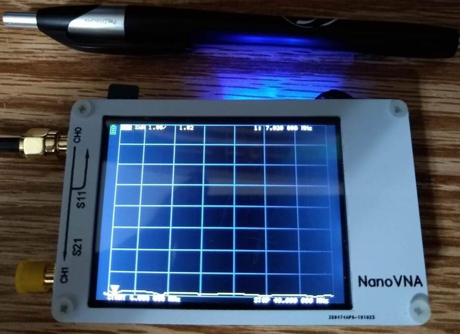
SWR scan very small at bottom of screen!
|
|
2019-12-16 I posted a photo of the QRPGuys scan I did on Dec 14 (shown below) in the Facebook EFHW Group and another ham suggested I download and try the NanoVNS-Saver software. So I did. This scan is from that. As he suggested the NanoVNA is easier to work with using that software. And also as he suggested, you can download the images. I'm very much a beginner but am starting to see how useful the NanoVNA really may be.
QRPGuys 40-10 EFHW SWR scan image downloaded from the NanoVNA-Saver v0.2.1. software.
|
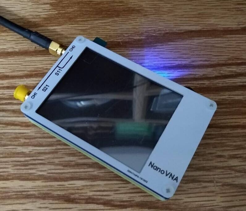
KKmoon NanoVNA Clone purchased on Amazon.
2019-12-14 Today, after a couple weeks waiting, my NanoVNA arrived! I've been watching YouTube videos about it and reading everything I could find so I was somewhat prepared. What is a NanoVNA? Well, the VNA stands for Vector Network Analyzer. I'm not sure I know what that is but it is generally a sophisticated piece of test equipment to test high speed networks. The Nano version is an inexpensive (about $50) and my primary interest is to check the SWR of various antennas.
|
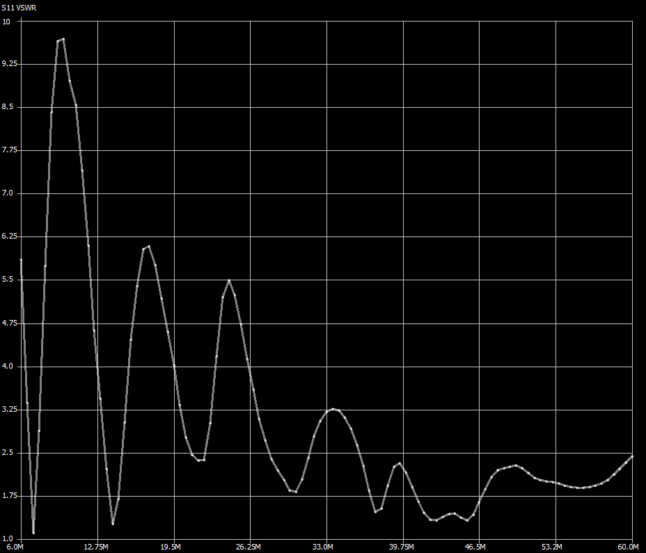
A couple hours after I got it I began to see one nice feature. It can show a very broad overview of the frequency performance of your antenna. That is because you can set it to sweep as narrow or as wide a frequency range as you want from 50Khz to 900Khz. That is particularly interesting when looking at an EFHW antenna. Below are the 6Mhz to 40Mhz traces for the MFJ-1984MP and QRPGuys 40-10 EFHW antennas as I have the set up currently. Both have pretty deep SWR dips in the 40, 20, 15 and 10 meter bands, approximately where they should be. You can use a pointer to focus in on a specific frequency or set the sweep range to cover just one band to see that band in more detail.

6-40Mhz SWR Trace of the MFJ-1984 MP EFHW Antenna. Dips are at 7.020, 13.820, 21.3 and 28.1 Mhz.
|
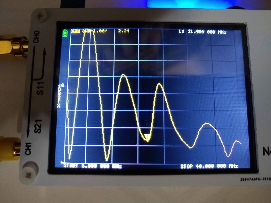
6-40Mhz SWR Trace of the QRPGuys 40-10 EFHW Antenna. Dips are at 7.02, 14.16, 21.98 and 30.14 Mhz.
|
Supposedly the NanoVNA can show much more information but that is where I am this evening.