Portable Vertical Antenna for 10-60 meters. |
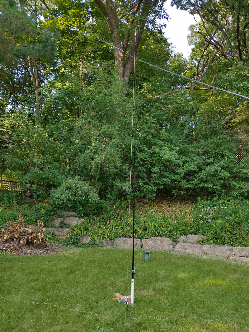
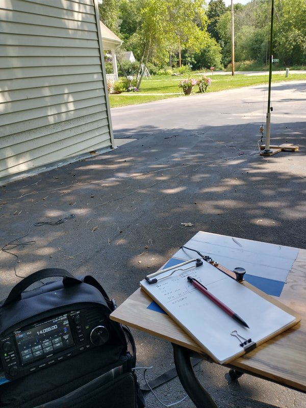
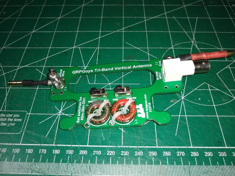
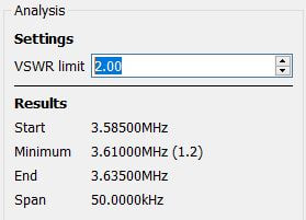
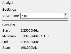
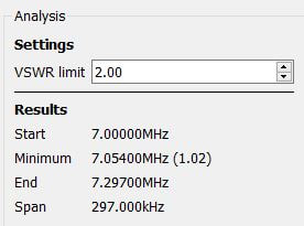
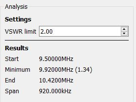
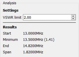
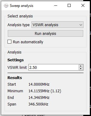
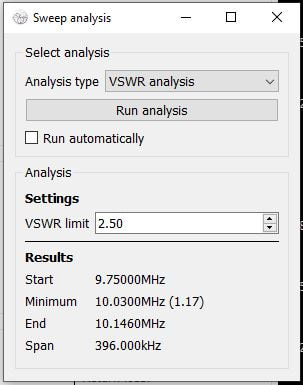
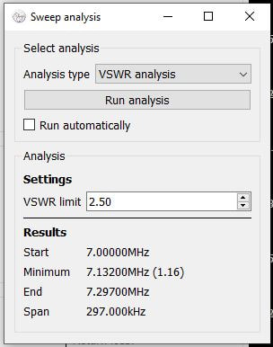
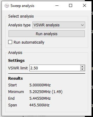
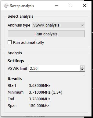
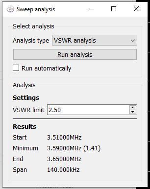
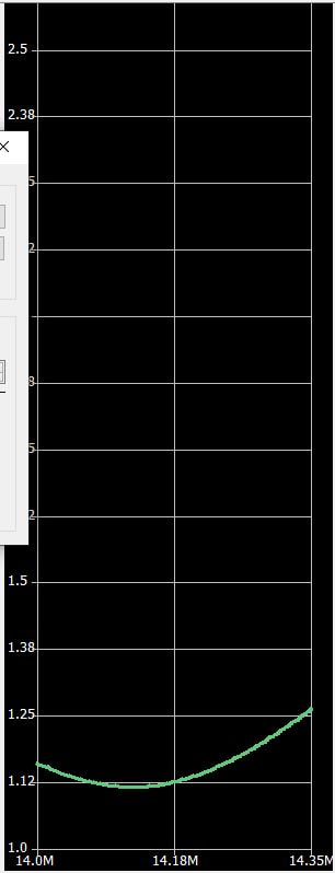
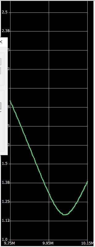
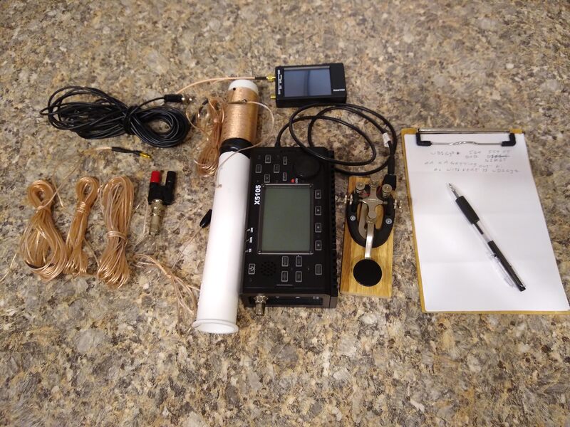
2021-07-24 if you read the "pages" below you will see the history of this antenna, dating back more than a year. It started with a QRP QSO with KW4JM back in January 2020 and has occupied hours of my time both tinkering with and using it since. Yesterday I had 18 QSOs with it in a park, 11 on 17m and 8 on 30 meters running ten watts and no tuner. The latest QSO was just a couple hours ago set up in my back yard. I had just tinkered one more time and wanted to be sure I hadn't ruined it. It now works on the eight bands between 40 and ten meters with an excellent SWR on all bands and has become one of my go-to antennas, especially for POTA activations. It really is not a compromise antenna unless you consider verticals as such. All antennas make compromises of some type and I'm sure this one is no exception. But in performance, I believe it will stand with the best of them, again considering that it is a ground mounted, bottom loaded vertical. I also need to give credit to the Wolf River Coils portable vertical. This is essentially the same antenna but made with wire. It also is very similar to the QRPGuys triband vertical. I learned a great deal from both of those. The WRC is my other primary go-to POTA antenna. In fact, I use it unless I really want the small, light weight and small size of this one to make carrying it easier.
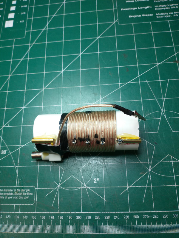
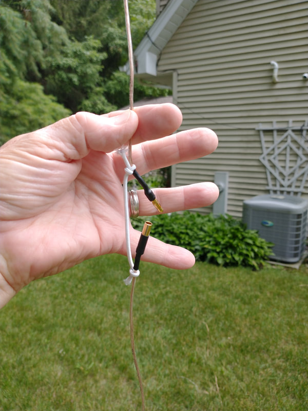
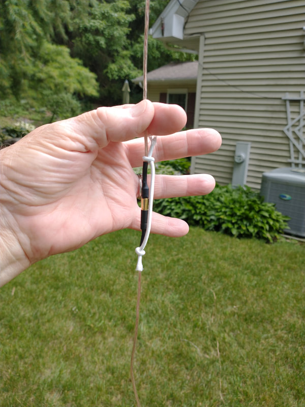
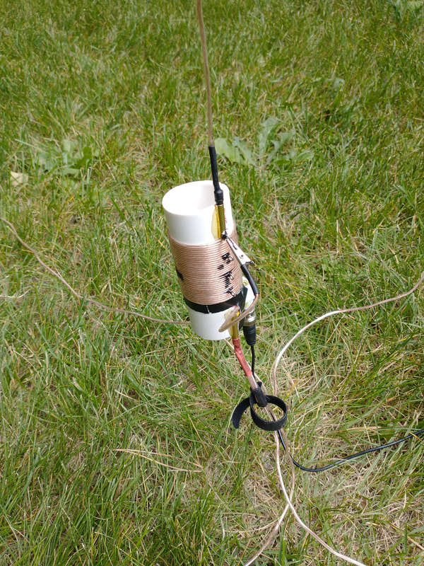
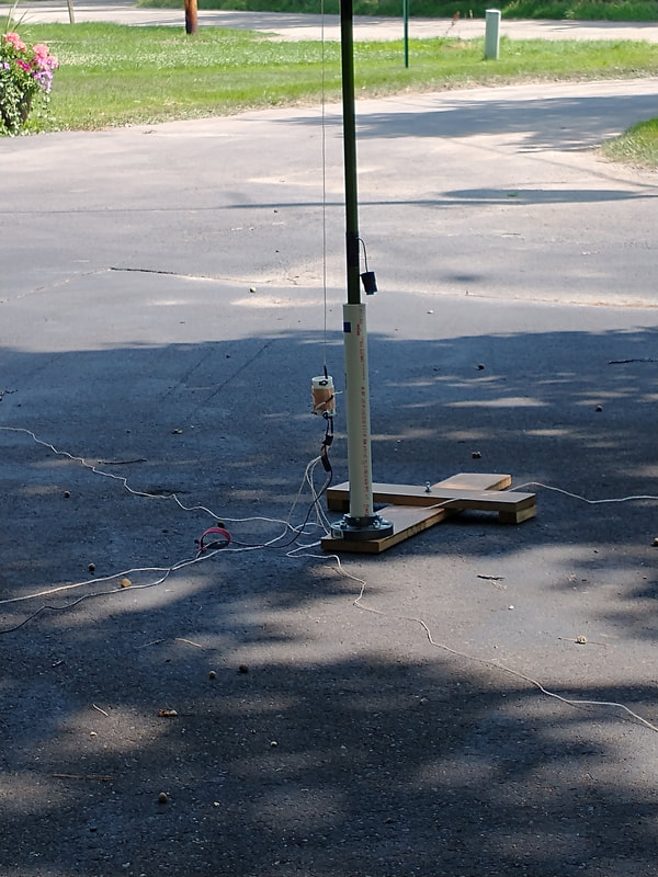
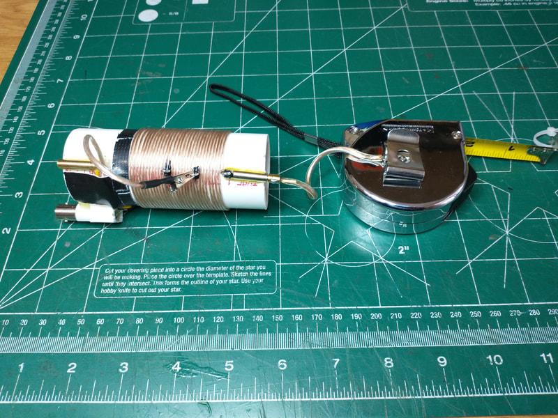
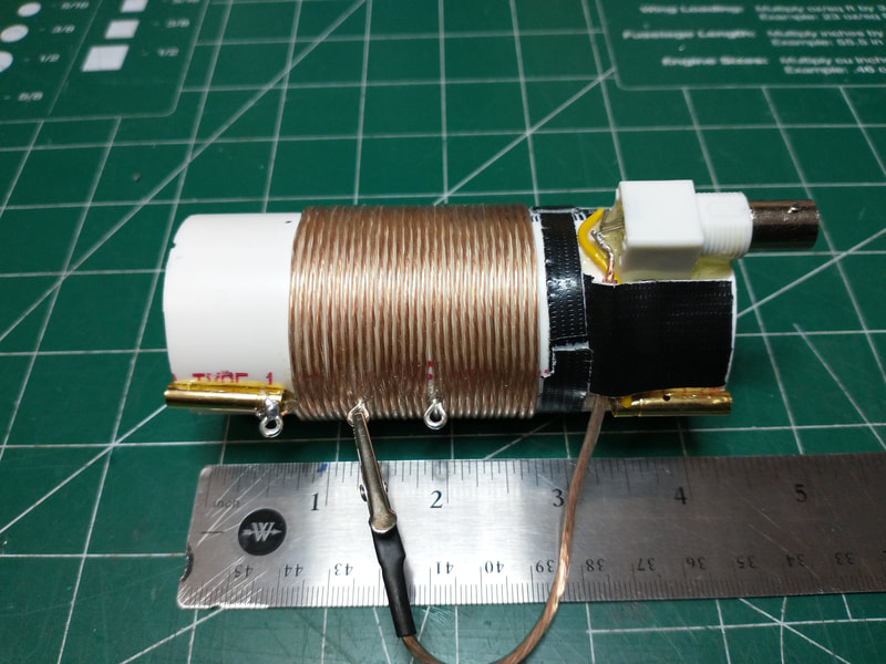
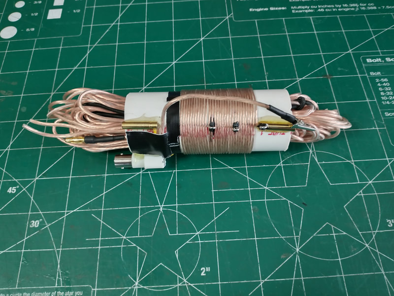
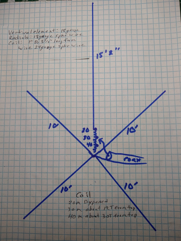
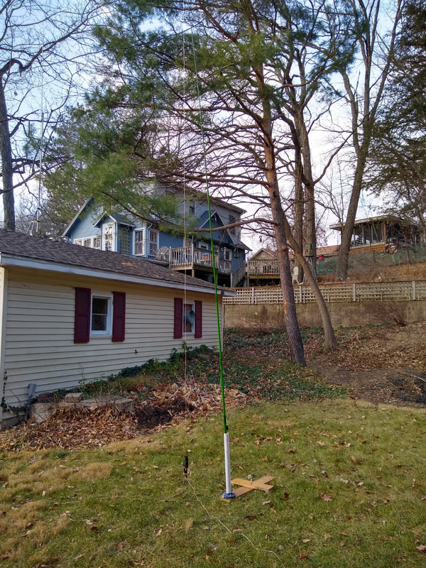
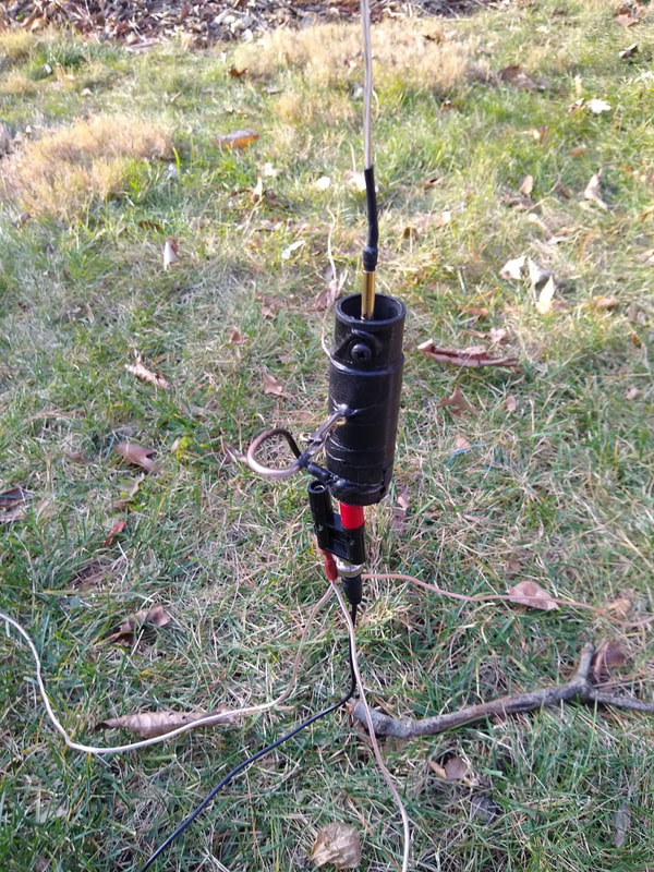
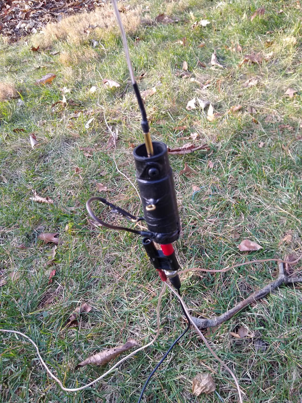
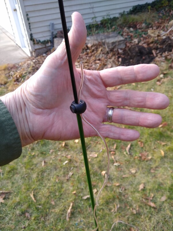
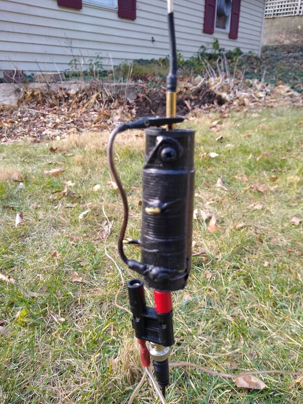
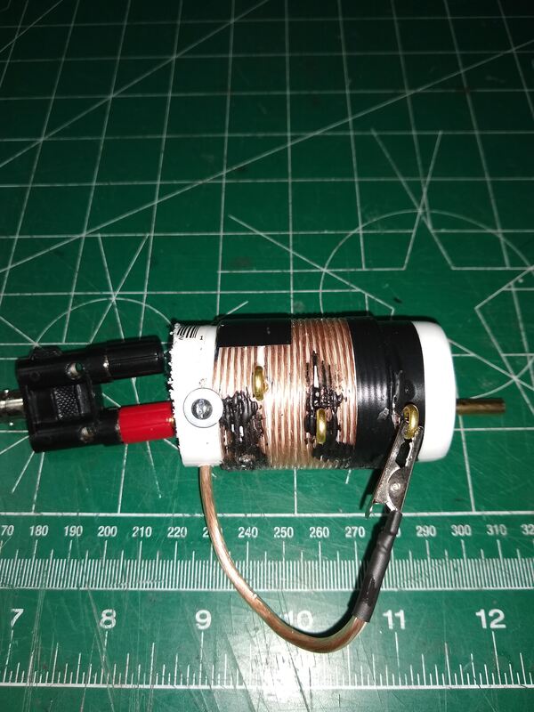
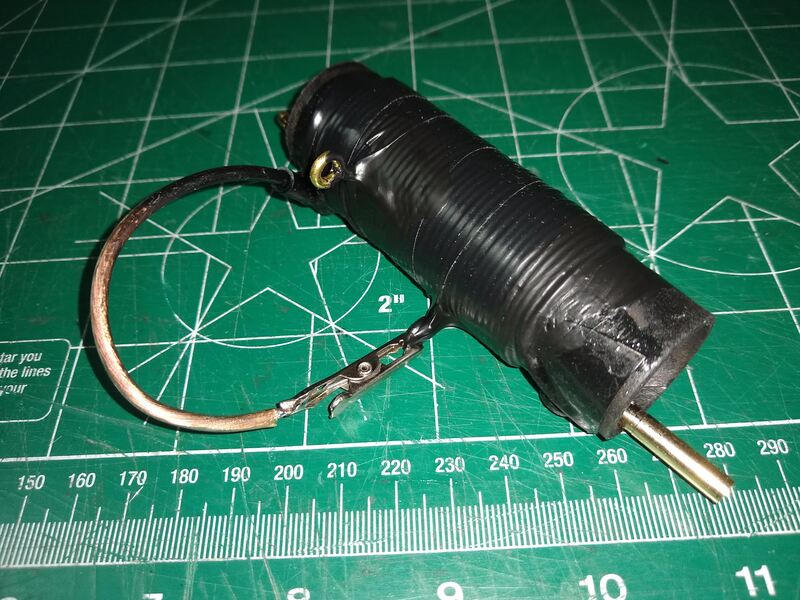
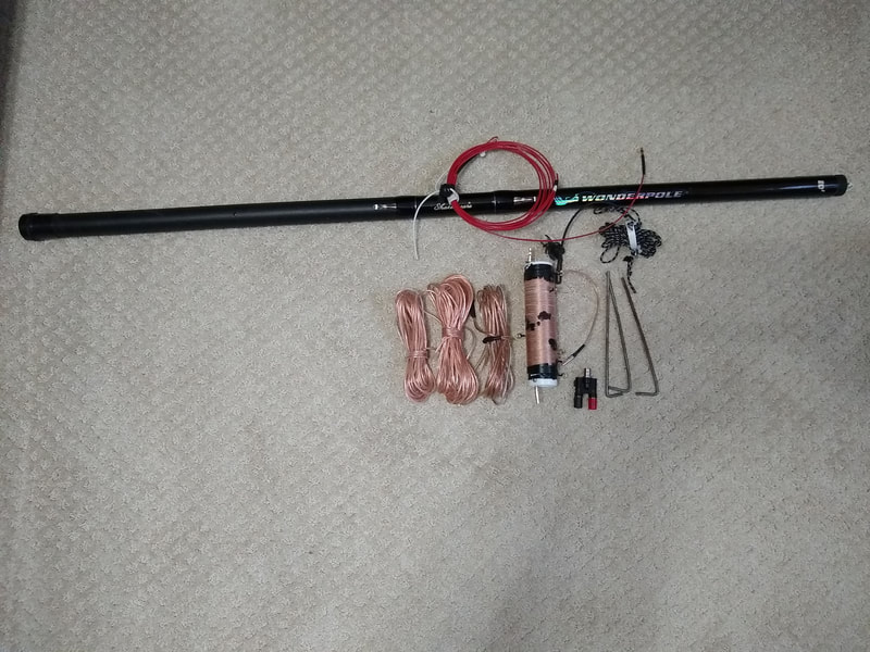
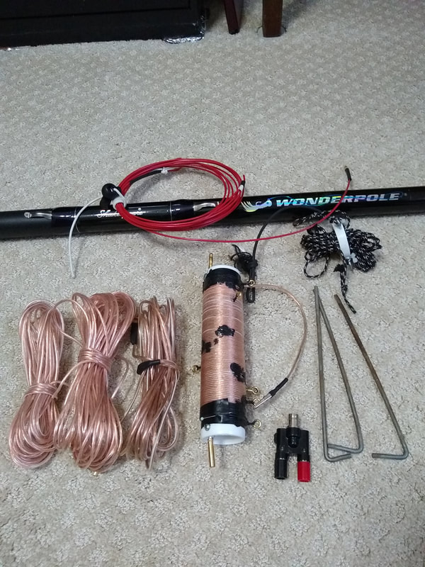
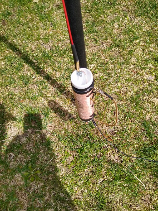
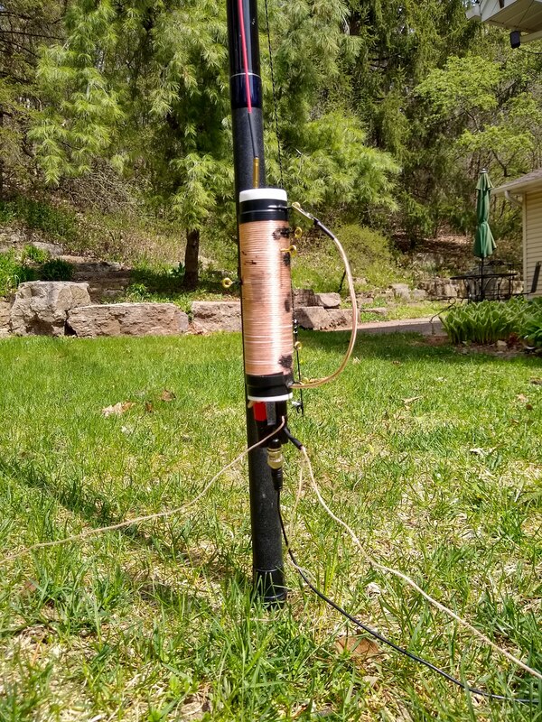
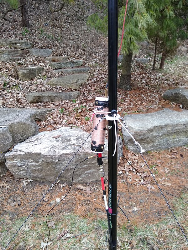
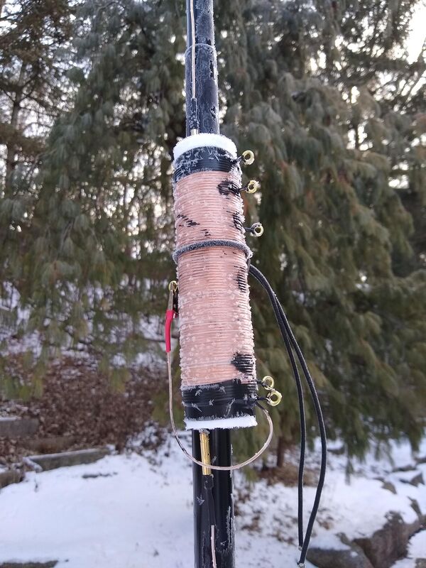
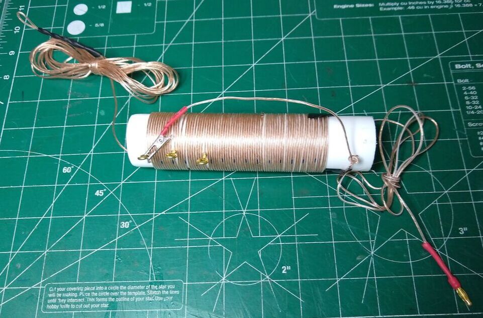
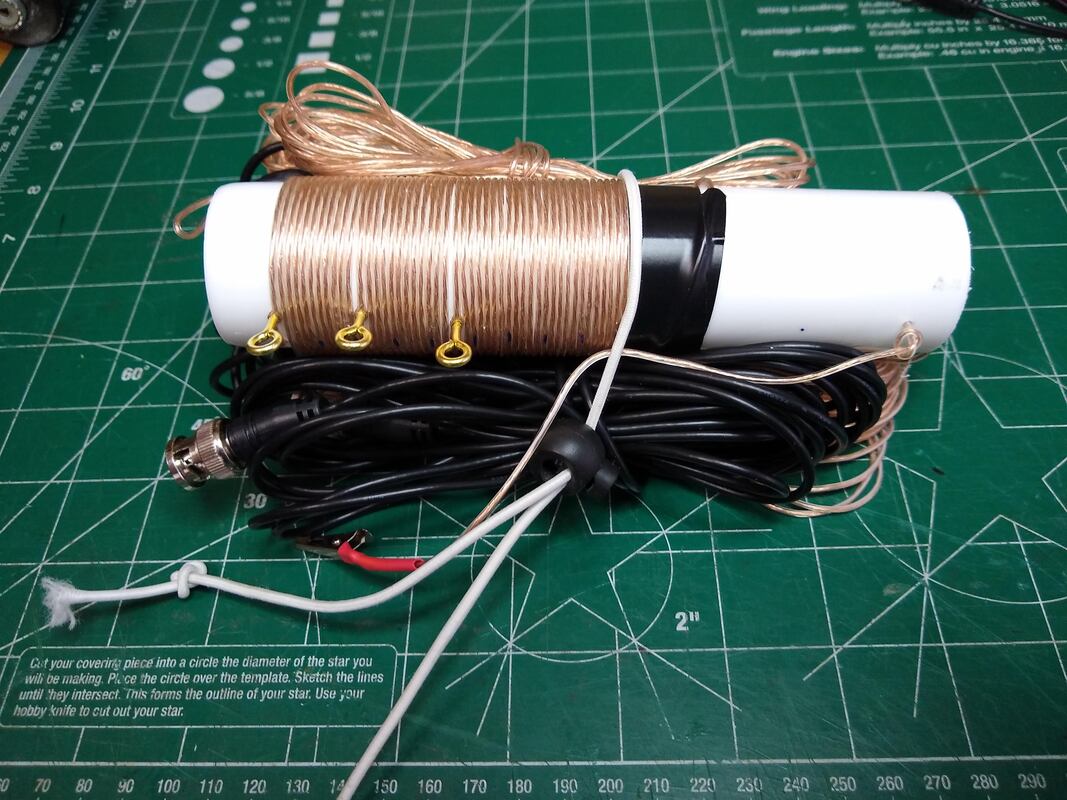
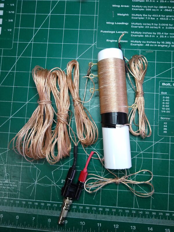
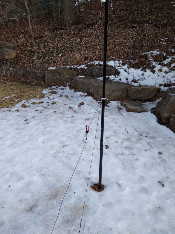
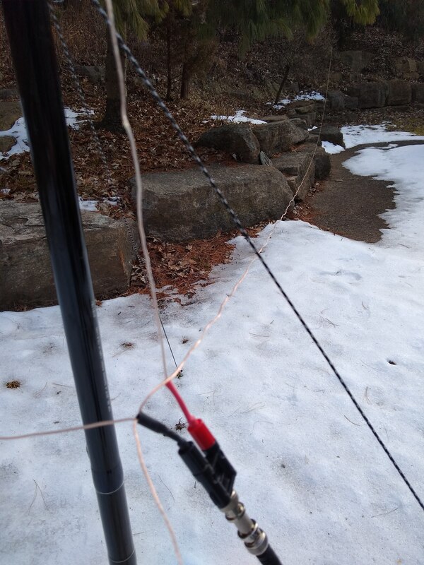
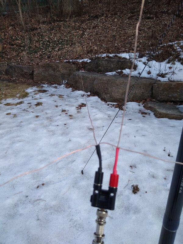
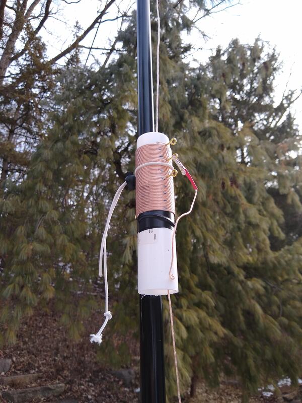
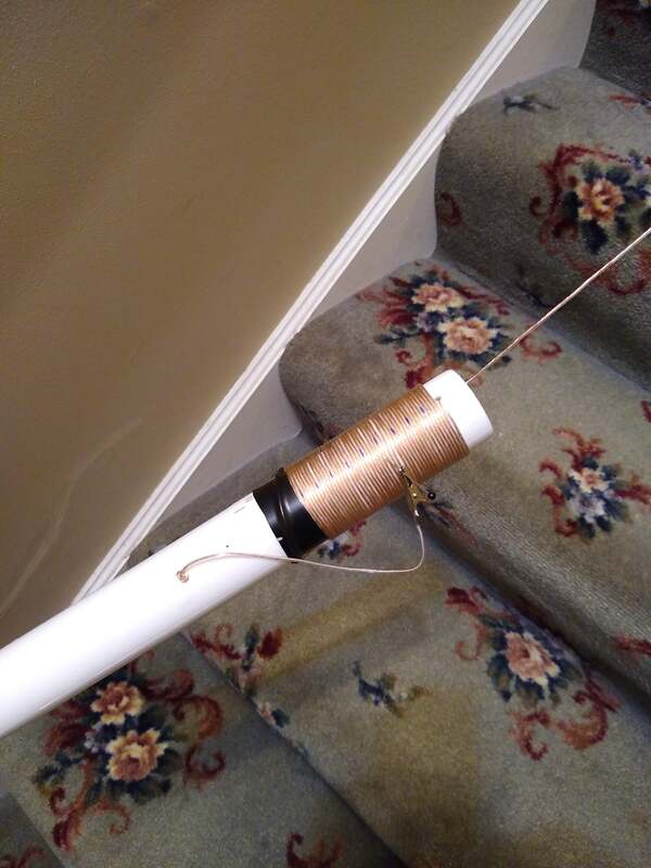
My latest tinker, was to add a 60 meter tap to the coil. So now with the whip set for 20 meters, that is the coil bypassed, taps on the coil it works on 20m, 30m, 40m and 60 meters. With the coil bypassed it has links in the vertical radiator so it can be used on 17m 15m, 12m adn ten meters. Yes, it does require you to lower the fiberglass (or other) support to open and close the taps, but in exchange you get a very light weight, small footprint (four ten foot radials), easy to set up, adjust and take down, inexpensive portable antenna. For a schematic of the latest version click here to download a pdf file. The photos below show some closeups of the coil and link construction.
|
2021-07-19 Today I decided to set up my DIY 17ft vertical with four ten ft counterpoise wires just to make sure I am happy with it. It is described in considerable detail below. It is a result of using my WRC TIA antenna with a 17 ft whip and building and using the QRPGuys Triband Vertical. They are essentially identical electrically. It has an excellent SWR on 20, 30 and 40 meters and though I only heard one signal on 40 meters this afternoon, I had a solid QSO with him, about 700 miles. Had another a few minutes later so I know it works!
There are three things I like about it compared with the other two. Mind you I do like the other two and probably use my WRC more than any other antenna for portable work, especially for POTA.
1) I built it! It's mine! There is something special about using your own creation even if based on the wisdom and experience of others.
2) It's small and light weight compared to the WRC and so more transportable. It will fit in my pack easily along with my radio and other essentials. With a string or rope you don't even need a pole. However I do take a 20 ft collapsible fiberglass fishing pole which straps on the side of my pack. So I really can close the car door and walk off with everything in one hand. A note here, including three tent pegs and a collar with guy ropes attached to stand it up.
3) Point tow is also true of the QRPGuys Triband vertical. The only advantage of my DIY one over the QRPGuys one is ease of initial tuning. It is easier for me to find the tap point on air wound coil than to adjust windings, maybe even turns on the toroids used by the QRPGuys one. But that's a minor thing.
|
The fact is all three are very good 20 meter portable antennas with a loading coil for use on the lower bands. Take your pick, you won't notice any difference in use!
|
2021-07-07 Well, I didn't get this antenna on 40 meters this afternoon because my DIY coil borrowed from the 17' version had a couple too few turns! And I don't think the form will take any more turns. Oh well, I was thinking of this as a test bed anyway so I'll make a new coil.
But even though bands were essentially dead with only sporadic life, I did catch N2BZD, 700 miles east, calling CQ on 30 meters at at 20:54UTC! He gave me 429 and he was about 539 in here with QSB causing us a lot of trouble. So, it works!
|
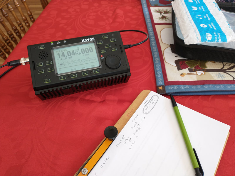
Setup for my test and success this afternoon.
|
2021-07-05 Last night as I was being kept awake by the neighborhood 4th of July bombardment, I got to thinking about antennas. Not a new thought for me, in fact I think about them a lot! Why? Well I like to operate portable, particularly doing POTA activations. I've got a great radio bag built around an ICOM IC-705. To do an activation all I need is to grab that bag, grab my antenna bag and hit the road. They're always ready to go. But wouldn't it be nice to have everything, including an antenna in that radio bag? Actually I have a 29' End Fed antenna in the bag but to support it I need a collapsible pole, which I have but it is too long and awkward for that bag.
In my antenna bag I have a WRC TIA Mini with two collars and a 17' whip. So it is good for 20 meters, 30 meters and 40 meters with no adjustments. Just set it up, pic a band, attach the coax and go. I love it and it is my antenna of choice. But it certainly won't fit in my radio bag. Also in the antenna bag is a version of the antenna described below. It has a 17' wire for the radiator and taps on a coil coil for 20, 30 and 40. In fact it is simply a wire version of the WRC. But it requires about a 20' pole which is also in the bag. Incompatible with my radio bag. An EFHW antenna for 40, 30 and 20 is also in the antenna bag which I set up as an inverted vee. But it too needs a pole. I use my 20' collapsible fiberglass one for that too.
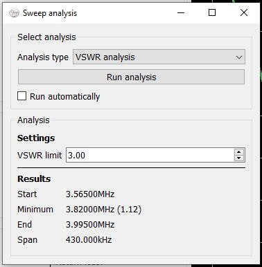
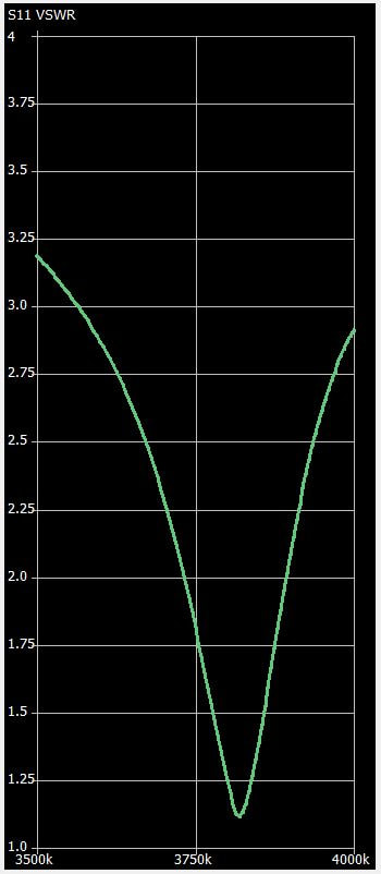
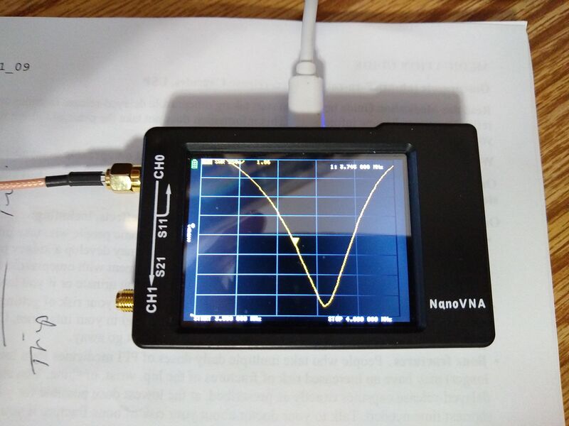
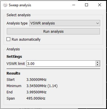
The new thought I had last night was to replace the 17' vertical wire radiator with a 102" (8-1/2') one. My WRC originally came with a 102" whip and worked pretty good so I know the concept works. So today I replaced the 17' radiator of my wire vertical with a 102" piece of wire, took it outside with my NanoVNA pretty quickly found the new tap positions for 20 and 30 (ran out of time to find 40) and Bingo, it resonates with a near 1:1 SWR on both bands. RBN heard me and gave good reports so I know it is radiating. Time prevented me from actually trying to make some contacts. I'll find 40 meters tomorrow and then give it a workout.
So, the final product is a 102" vertical wire, a hand would tapped loading coil and four ten foot counterpoise wires. And my 14' collapsible fiberglass fishing pole which measures just 22" long when collapsed lashes neatly to my radio bag. So with the wires and coil in a plastic bag inside and the pole on the outside, I now have two reasonable antennas in the bag. Grab one bag and go. POTA, here we come!
|
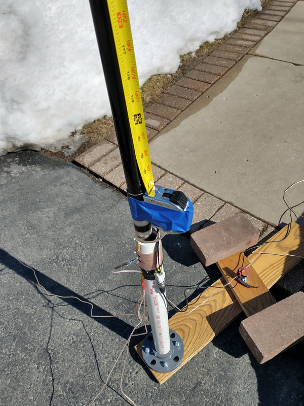
2021-02-26 something got me thinking the other day about replacing the vertical wire radiator on my 1/4 wave 20 meter antenna with a tape measure! Don't ask me why, I don't know. Perhaps it's Covid-19.... My mind is falling apart? Anyway I imagined that it would make it easier to put up and take down with the tape extending and retracting "automatically." So I went to our local home store looking for a cheap, small 20' tape measure. Well, cheap I found. It was 16' long and not particularly small with it's 3/4" wide tape.
|
I set about seeing if I could make it work. Step one was to see whether there was a good electrical connection between the case and the tape. There is. Step two was to figure out how to mount it on the pole and attach it to my coil. I was able to connect a short pigtail with a bullet connecter plug on one end to the screw that holds the belt clip in place. All I had to do to connect it electrically is to plug that bullet plug into the bullet jack on my coil in place of the normal wire element.
Step three was to figure out how to attach it to my fiberglass mast. I never really solved that but using painters tape I was able to mount it temporarily to see if the thing would even work! My first eye-opener was that the tape measure exerts an increasing about of tension to the pole as it is extended. That was a concern all along. But I managed to get it all the way out without breaking the fishing pole mast! I could see right away that I was heading for trouble. But I want to the next step.
Step four was to see it it worked! So I connected the coil to my xiegu x5105 with a length of RG-174 coax and checked resonance on 20 meters. It was excellent, about 1:1 SWR across most of the band, just as with the wire element. Tuning around several good signals were present. As I zeroed in on one to give him a call, signals dropped dramatically. Looking out the window, there was my mast, on the ground. Another wakeup moment. That 3/4" tape has considerable more wind resistance than the 18 gauge wire!
At that point I scrapped the idea. It was clearly more cumbersome and heavy than using the wire element. Mounting the tape measure was going to be involved and my mast was at risk from bending along with the increased wind resistance. BUT I know it would have made contacts, likely with no detectable gain or loss compared with the wire element. Conclusions? It works. You don't gain much if anything. The effort was fun. I've got another cheap tape measure! Oh, it only cost me $3.95 before rebate from the store, plus gas! I'm happy.
2021-02-19 I've been working on the improved portable wire vertical the past four days. Though I'm never "done" I now declare this one very close to that! The pictures below show the result. The completed slip-on loading coil is in the first photo. The coil assembly weights just 4 oz, not bad since it is wound and assembled on a 4" piece of schedule 40 1-1/4 PVC. The four 10' counterpoise wires and vertical radiator also weigh 4 oz, so the whole thing is just half a pound. An unexpected bonus is that the counterpoise and radiator can be stuffed inside the coil assemble so it takes up minimal space in my bag. All that's required to put it on the air is some coax and something to suspend it from. I use RG-174 coax and a 20' fiberglass collapsible fishing pole resulting in a total weight of 1.3 lbs.
I've made 15 contacts with it set up in my driveway over the past four days. My rig was my 5 watt x5105. Four of those were SSB, three on 40m and one on 20m. The rest were CW; three on 40, one on 30m and seven on 20m. The furthest distance was 2,435 miles with a contest station in Bonaire in the ARRL DX CW contest this morning on 20m.
I've been using an almost identical vertical on my POTA activations for quite a while now so I know what the antenna can do and am very pleased with it. My setup for testing this antenna was with my x-5105 on our dining room table (with my wife's approval!) and the antenna setting on the edge of our driveway about 35 feet away fed via two 25' lengths of RG-174 coax. That setup works so well I may decide to sell my Icom IC-7300 and G90, take down my EFHW and G5RV antennas and just operate from the dining room! I think I'm kidding! But it does prove to me that I don't need much of a station to have a lot of fun. And with such a simple antenna I don't really need much acreage or even a permanent antenna.
2021-02-17 Yesterday I finally received the 20' fiberglass mast I ordered from Amazon. I wanted to try it because the O.D. of the bottom section is just a bit over 1" and it is of fiberglass. My aim was to wind the loading coil for my 20m vertical right on that bottom section. So I did that. Since on version of my previous coils was on a 1" o.d. cardboard form I patterned the new coil after that (failed to take any pictures) so winding the coil was quick.
I knew before hand I had several issues to overcome. One was how to do the taps as I can't have anything protruding through the section wall. Another issues was how to make the coax and counterpoise connections without making the result both awkward to connect to but also I didn't want anything seriously protruding out from the pole as a key objective is that it would be easy to pack and carry. I gave up as I really couldn't come up with any ways to address those two issues.
But before giving up I did jury-rig it together and made it work, making one contact on 40m using my qrp rig. It tuned perfectly on 20 and 30 meters with no detectable interaction with the fiberglass pole. But I could not get 40 meters to tune properly. It always presented me with two very similar SWR dips, about a megahertz apart and I couldn't find the tap location that actually resonated right inside the 40m band. SWR was about 2.5:1 across the entire band telling me something was "loading it". My tuner would handle it but it clearly wasn't right. That along with the other two problems mentioned above caused me to give it up for now.
2020-11-23 The paragraphs and pictures below show the background for what I'm going to describe now, more less the culmination of my various experiments and experiences. A 1/4 wavelength antenna is a very good antenna not only on it's native frequency, in this case 20 meters but on lower bands as well with appropriate loading coils. For antennas I make primarily for portable use I have settled on a bottom loaded version, the loading coil is right at the bottom of the vertical element. An often used and some think better performing one has the loading coil raised from the bottom, maybe three or four feet below the coil and the rest of the 1/4 wavelength radiator above it. Some claim these are better performing. They also generally use elevated radials rather than the radials laid right on the ground. I played with that approach but found the added complexity in deploying it, especially when portable, not worth any performance gain it hay have given me. So I'm "stuck" on the bottom loaded vertical which I will describe here.
Design Description
|
The antenna consists of three basic parts: 1) the vertical radiator. 2) the loading coil. 3) radials or counterpoise wires.
First the vertical radiator. Mine is 15' 2" long, made from 18 gauge speaker wire and one end is connected to the top of the coil.
Second, the loading coil. Mine is wound on the cardboard core from an empty roll of kitchen wrap. The "form" is about 4 inches long and about 1 in in outside diameter. The winding consists of about 40 turns of 24 gauge speaker wire tight wound with three taps, one at the very top. One about 12 turns from the top for 30 meters and one about 30 turns from the top for 40 meters. There is a pigtail (cut from a piece of 18 gauge speaker wire) with an alligator clip attached to the center conductor of the coax feedline (NOT to the bottom of the coil) long enough to clip on the very top of the coil (effectively bypassing the coil) for 20 meters. The tap is moved from the top to the 12 turn down for 30 meters and to the 30 turn tap for 40 meters.
Third, the four 10 foot counterpoise wires are soldered together at that point and then connected to the shield of the coax cable.
Construction TipsThere are any number of ways to fabricate this. Note. It is very important that the bottom of the coil is NOT connected to anything. It is floating.
One way to connect the vertical radiator to the top of the coil is to solder it to the top of the coil. and anchor it with a small bolt. I opted to install a banana jack to the top of the form and terminate the coil to that jack. Then I put a banana plug on the bottom of the radiator so I can simply plug it in.
|
One of "biggest" challenges is how to physically mount and connect the the coax center conductor to the pigtail and shield to the radials and keep in place physically. A very simple, inexpensive but almost indispensable adaptor is known by Amazon as a "BNC Female to Dual 4mm Banana Female Jack Socket Binding Post Adapter." To use it I attached a banana plug to a small bolt through the coil form (not touching nor connected to the winding). I also attached the pigtail to that bolt. Then I can simply plug the coil form on to the positive banana binding post which connects the pigtail to the center conductor of the coax which is connected to the BNC connector.
I attached the joined end of the 10' counterpoise wires to a banana plug. With that I simply plug the counterpoise bundle into the ground or shield binding post on the banana adaptor and they are connected to the shield of the coax.
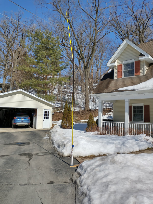
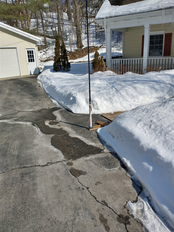
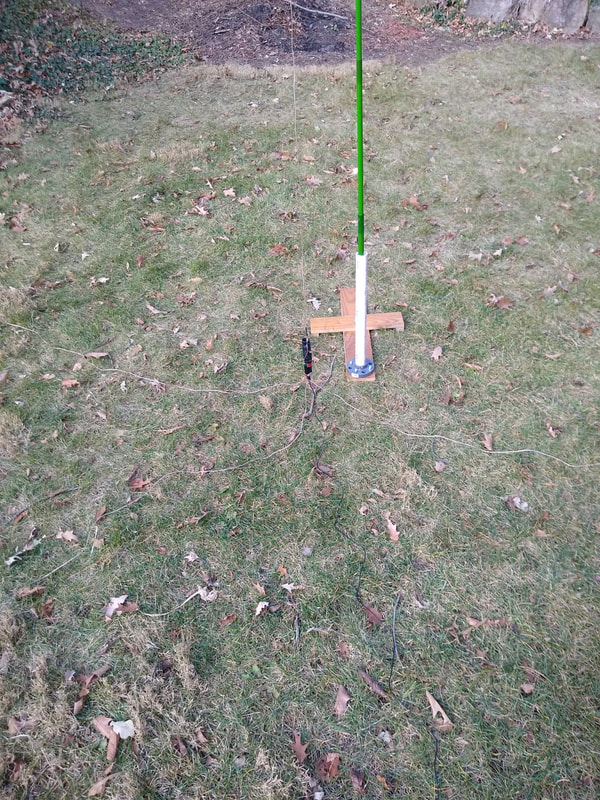
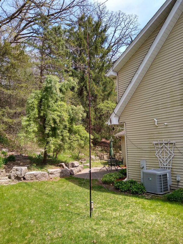
To deploy the antenna, to deploy the antenna, simply suspend it to the bottom is a few inches above ground by hanging it from a tree, attaching it to a long fiberglass fishing pole or whatever, spread out the four counterpoise wires, connect the coax to your radio and go! The pictures below show my completed antenna.
The last step is tuning the antenna. This will take a little experimenting. Start by making your vertical radiator a maybe six inches longer than mentioned above and fold about three inches back on itself and tape it there. This gives you room to adjust it, longer or shorter. Then plug the vertical element and counterpoise wires directly into the bnc-banana binding post adapter without the coil. Find the resonant frequency by finding the lowest SWR frequency. An antenna analyzer will make this fairly easy. It should be pretty close to or even in the 20 meter band. If it is to high in frequency, open the fold and lengthen it a little, maybe an inch at a time. If it is too low in frequency, fold back a bit more of the top onto itself, again about an inch at a time. Using this technique you should be able to get it to about the center of the 20 meter band with a very low SWR.
Now insert the coil between the bottom of the vertical radiator and the bnc-banana binding post adaptor. Clip the pigtail to the bottom of the radiator and check for resonant frequency. It should be a little lower because the length of the pigtail had been added to the vertical radiator length. Fix that by adjusting the fold-back at the top of the radiator. With 20 meters looking good it's time to move to 30 and 20 meters.
A simple, non-destructive way to find the tap location is to use a straight pin or needle. Clip it into the alligator clip on the pigtail and then carefully push the pin through the insulation of a winding close to where you think it my end up. Check the SWR and move the pin toward the top or bottom a turn or two until you find the magic spot. MARK it with a felt tip marker. Repeat the process for the other band.
The final step is to get some tiny screw eyes and carefully screw then through the winding where you marked it and into the coil form. Put one in the very top winding, one at the 30 meter position and one at the 40 meter position. Be careful not to break the winding but go through it. Check your antenna on all three bands and adjust the screw eyes if needed. You're done!
2020-05-17 Since I have three coil options for this antenna: the original wound on a 1-1/2 inch core, One wound on a one inch cardboard core from some kitchen wrap, and the QRPGuys 3-band vertical, I decided to cut a second radiator and radials. I cut the radiator 15 ft long. Then I got to thinking that supposedly ground radials don't need to be cut for each band. In fact the QRPGuys antenna suggest four ten foot radials. So i cut three ten foot ones and set up the antenna to test it.
It turns out that the vertical radiator needs to be several inches longer as the resonant frequency has increased on all three bands. On 20 meters, for example it went from 14.070 mhz to 14.8 mhz. Is that due to the radial length change? I'm not sure but will do more testing - not today as it is raining! I think I'll start by simply using the original radials and see whether or how that changes the resonant frequency.
I don't' have an easy way to compare performance with the different radials but I made several contacts with the 10 ft ones and didn't feel like anything was different from the other set of radials. So my feeling is that performance is very similar. Never a dull moment when playing with antennas!
2020-05-14 Several weeks ago my wife finished a box of kitchen wrap and threw the cardboard core away. But, always looking for something "useful" I grabbed it. Today the "something useful" came to mind a loading coil for my vertical. Its probably not as robust as the one built on plastic, but after a bit of tweaking it works just as well as the original. It is shown in the center below. The one on the left is my "original" but trimmed down for 40, 30 and 20 meters only. And the QRP Guys 3-Band vertical coil adapted for this antenna is shown at right. All three are interchangeable and seem to have nearly identical characteristics. So I have three coils for my vertical! Presumably all but the QRPGuys one can handle more than 20 watts.
2020-05-09 Well, I made another change to this antenna and put it up again! Like a lot of things in life, a DIY antenna is never "completed". The change is small but I think significant. I replaced the #20 Teflon insulated wire I was using for the radiator with 18-gauge RCA speaker wire. I noticed that the wire was not tolerating the bending at the lower end well. Hopefully the larger and more flexible speaker wire will fare better. I put a fairly long piece of shrink wrap tubing over the banana plug and wire to reduce the flexing right at the solder joint. The antenna still tunes up just fine, in fact I didn't notice any change at all.
2020-05-07 Today I decided to set up the bottom loaded version of this antenna again and see how it performed. I made two small changes because the #24 speaker wire pig tail broke at the alligator clip and one of the #24 radials broke. So I replaced the radials and pigtail with #18 RCA speaker wire. It feels a bit more robust now! I used my 20' Shakespeare Wonderpole to suspend it.
It had excellent SWR on 20, 30 and 40 meters and I made four contacts on 40 meters, and two each on 30 and 20 meters. One of the 20 meter ones was with N0OI in California, 1620 miles west. I was very pleased with the antenna. It moved up a notch in my list of "favorites!"
2020-03-31 Well I decided today to spend some time tuning my bottom loaded version of this vertical antenna. I kind of hate to admit it, but I spent nearly the entire day with this thing. Got lots of exercise going out to the antenna and back into the house to check the results or make a change in tap locations on the coil! Making an antenna with a tapped loading coil is not for the faint of heart and mind AND body!
I started by clipping to the 20 meter tap at the top of the coil and then adjusting the length of the radiator. Once I got that where I thought I wanted it I began searching for the best locations for each of the four taps; 30, 40, 60 and 80 meters. I used a straight pin to puncture the coil wire until I found the best tap location. Then I marked that with a magic marker brought the coil inside and moved the screw eye to that location. When I got all done I went back over them. All were great except the 20 meter one which was resonant below the band at 13.5mhz!! It was supper time so I just stopped! I could swear I had it in the band.... But that wouldn't change anything! I had three radials laid on the ground, one 16', one 22' and one 33'. I initially had three 33' radials but the SWR seemed worse with those. The whole thing was mounted on a fiberglass fishing pole 20' long.
Tonight I got on 40 meters and was onlly able to snag one QSO, with KC5F 570 miles southeast in North Carolina. He gave me a 599. He was 577 in here. He was running 60 watts. When I told him I was 20 watts he replied, "WOW!" Not sure why I couldn't raise anyone else. Reverse Beacon Network gave me varying results but most below 10db S/N. Earlier today the bands were not good at all so I need to give this thing more time to prove or disprove itself.
2020-03-18 I replaced the 24 gauge wire with 18 gauge and problem solved! Not sure I understand what happened, but it works again.
But as I have thought about actually using it in the field, I am thinking a bottom loaded version would be much easier to deploy with the radials lying right on the ground instead of elevated. To today I made a minor change in my banana plug/jack placement so I can easily move the bottom wire to the top thus extending the top element. I had to retune it for 20 meters by shortening the top element with the three radials lying on the ground. That worked well and the resulting SWR and according to the Reverse Beacon Network actually radiates fairly well. However, when I began checking other bands by moving the tap, I have a problem. The taps are not on the correct turn of the coil for the bands with the new arrangement. I'm getting frustrated with this antenna. It is a good antenna, but having a non-fine tunable coil is a problem. I'll mull it over a while and use my Wolf River Coils antenna in the meantime!
2020-02-26 I got the bright idea today to replace the 24 gauge speaker wire I used for the upper and lower elements with a more robust 26 gauge wire I had left over from another antenna. So I cut the pieced identical to the speaker wire ones I wanted to replace and hung it up again. The resonant frequency shifted up considerably! I haven't' had time to investigate further. Could it be the wire Size? Maybe the material itself? The speaker wire is soft drawn many-stranded wire. The replacement has far fewer threads in the strand and gets its strength from a special fiber cord through the middle. It is not nearly as flexible as the speaker wire. I plan to do some experiments to see if I can determine the cause of the shift.
|
2020-02-16 I've been wondering how this antenna would change if the radials were on the ground. So today I dropped them to the ground, making no other changes and compared the signals reported on the Reverse Beacon Network.
When I sent CQ with the radials elevated as they have been for all my development work and all previous QSOs I was heard by twelve stations. When I dropped them to the ground (actually to the snow!), not a single station heard me. But when I returned them to their elevated position I immediately got reports again, comparable with the previous ones.
I also noticed that the SWR was considerably higher with the radials on the ground. I'm guessing that had I tuned it up with ground radials the SWR would have been fine with them. Whether it would have radiated as well as with the elevated ones, I don't know. I may experiment with my Wolf River Coils antenna sometime which is very similar in design but easier to change the "taps" on the coil by simply moving the sliding collar.
As noted above in the log of contacts I was able to have two good 30 meter QSOs with it this morning, with the elevated radials. I still have not managed any QSOs on either 60 meters and only one on 80 meters. 20, 30 and 40 seem productive. I'll keep trying on 60 meters.
|
2020-02-15 OK, I think I have conquered this thing. I've been struggling with it the past few days as I'd think I had the taps in the right place only to think otherwise the next time I put it up. Much to my embarrassment the problem was that I mixed up the top and bottom elements with the ones for my QRPGuys Tri-band vertical. Turns out a few inches makes a difference! So today I sort of started over by selecting the top element (11' 3" long) and then adjusted the bottom element (48") until the antenna resonated right where I wanted it on 20 meters, which bypasses the coil entirely. Then I worked my way down the taps from there. Most of them were where they needed to be but a couple needed changing. I also added a tap for the lower part of 75 meters. It would take at least three taps to cover the whole 75/80 meter band. But I'm mostly interested in the CW portion. and the tuner in both my G90 and x5105 can compensate for the off-frequency SWR. The charts below show what the antenna looks like now. I wrote the lengths of the top (11'3") and bottom(48") elements on the inside of the ends of the coil form so I can do it right next time! I think I'm done!
Here are the inductance measurements of the taps measured from the top 20 meter tap down: 20mtrs: .41uh; 30mtrs: 5.67uh; 40mtrs: 14.34uh; 60mtrs: 31.80uh; 80mtrs: 75.75uh. I'm sure my measuring instrument is not that accurate but it's what I have so there are the numbers.
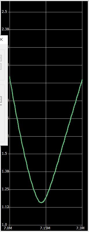
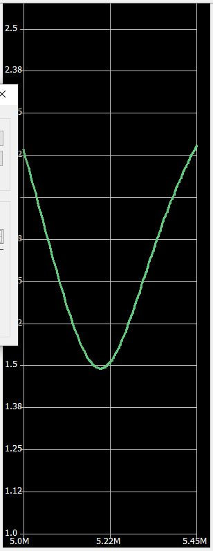
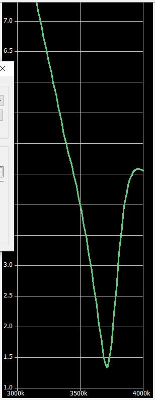
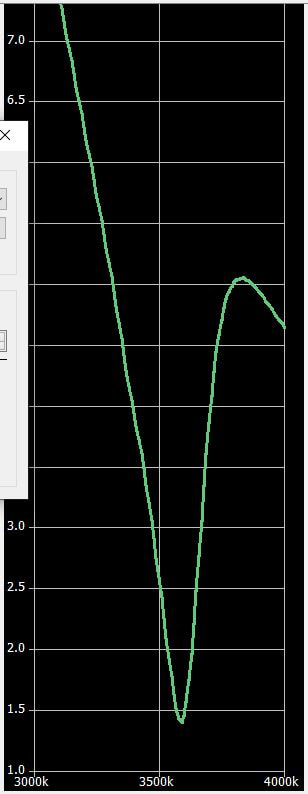
2020-02-14 Did a bit more tweaking of the taps on the coil today. It now resonates at 3.507, 5.28, 6.94, 10.22 and 14.07. SWR is usable on all bands except the middle to higher end of 75 meters. I marked another tap location to cover that but didn't add it. 40 is still a bit low. Need to move that tap one more turn up the coil. But you get tired of fiddling with it after a while! :-) As the log shows above, it works.
|
2020-02-12 In spite of the fact that it was 19 degrees outside this morning, I swapped out the QRPGuys antenna for this one. The fiberglass Wonderpole was not happy to collapse until I warmed up the slip joints with my hands, which are now in need of being warmed up! But I got it up. To start testing I clipped the pigtail to the end of the 75th turn and came inside to check it out. Amazing! It resonates at 3.8 mhz!
|
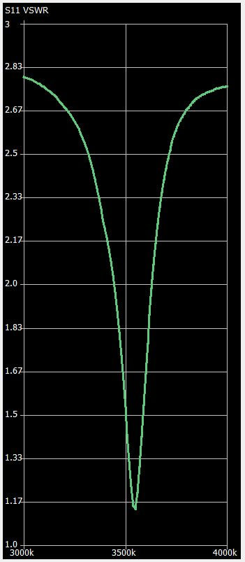
As expected the bandwidth is very narrow. I recall my screwdriver mobile antenna being like that on 80 meters as well. My G90 tuner can bring the SWR down but I'm guessing its efficiency is not great even at its resonant frequency. It would be nice if its resonant frequency were a bit lower frequency as I'm most likely to use it in the CW portion. I may add a few turns to see if I can get it down to about 3.55mhz or so.
|
Well, couldn't wait so took the antenna down and added ten more turns, all I could get on the form! 85 total turns, 75uh. Put it back up and checked it again. Right on! Resonates at 3.54mhz, right where I wanted it. Done! Maybe. I keep thinking of things to look into or try. NO, I'm not going after 160 meters! Sorry. :-)
I declare it ready for the big leagues!
|
|
2020-02-11 tonight I added more turns to my loading coil bringing the total number to 75. It measures 62uh total inductance. Now tomorrow, if I can survive the cold that's predicted, I'll replace my QRPGuys 3 band vertical with this and see if it will resonate on 80 meters. Will be interesting to see how it performs if I am successful.
I asked recently on Facebook about people's experiences or thoughts on elevated vs. ground radials. As will all things antenna, the feedback was mixed. The general opinion seemed to be that in the field, whatever advantage their might be to elevated, tuned radials was offset by the somewhat more complicated use of them. So most just go with ground radials. I experimented a bit yesterday with my WRC TIA using three 16'. 23' and 33' radials rather than the supplied three 33' ones. Not sure I could tell any difference... All were on the ground.
|
|
2020-02-07 Like I said, a DIY antenna is never "finished!" To prove the point I did a bit more work on it today. I added a 60 meter tap and replaced the banana plug on the bottom element, putting red shrink tubing on it to make clear it is the hot wire! Then I strung it up again, being a bit more careful with the radials, which by the way are elevated. I draped them over shrubs and tied them to twigs to keep them a couple feet off the ground. Then, I had a QSO with F6HKA in France on 20 meters CW! Above is my total log of contacts with this antenna to date. SWR is almost flat on all bands except the top end of 40 which rises to near 3:1. Center frequency could probably be moved up a little but I favor the bottom end of the band so am happy with it.
The coil form is 1-1/2 inch diameter and about 7 inches long as shown. It could be trimmed by a couple inches but I left it long just in case I want to try to add 80 meters later. The coil itself is tight wound with the #24 speaker wire and is 3 inches long overall. The taps are as follows:
|
The finished product, including 25 feet or RG-174 coax, weighs just ten ounces and after putting it up several times now, it took me just shy of ten minutes to set up, a few minutes ago on my Wonderpole, which was already standing supporting my 4020 trap inverted vee.
2020-02-06 Well, today I think I "finished" this KW4JM vertical multi-band antenna. Of course a DIY antenna is never finished, but I think this one is at a "steady state" for a while. It is almost identical to where it was yesterday with a bit of tweaking of the windings for each band and cutting off the "sewer pipe" coil form. The whole thing weighs just under 6 oz.
Here are the details:
- Coil form is 6-1/2 inches long.
- The coil has 47 turns, of which 23 are currently used as shown in the picture. I didn't implement 60 meters.
- 20 meter tap (screw eye) is at the top, in the first turn.
- 30 meter tap is in the 11th turn, 3uh down from the top.
- 40 meter tap is in the 23rd turn, 14uh from the top
- The radiating element measures 11' 10" long from the top of the coil form.
- The bottom element measures 48" from the alligator clip to the banana plug.
- The three radials measure 33', 23' and 16'
- SWR is essentially 1:1 across the entire 20 meter band, below 1.5:1 across the entire 40 meter band and around 2:1 on the 30 meter band.
The measurements can vary a little without much impact on the antenna. To set it up I suggest cutting the top element slightly until it resonates near the center of the 20 meter band with the very tip of the coil tapped.
Then you can find the tap location for the other bands without messing with the length of either the top or bottom elements. A simple way to fine the tap locations is by carefully pushing a straight pin through the insulation and into the wire, being careful not to damage the wire. I marked my coil with a felt tipped pen every five turns from the top to make it easier to tell where I was with my straight pin.
Once you have the tap locations, I used a scratch awl from my T-Square to carefully push a hole through the winding and make an indentation in the form. Then moved the windings to either side of the resulting dimple and drilled a 5/64 inch hole through the form. Then I moved the winding over that hole and using the awl carefully enlarged hole through the wire. Finally, I was able to screw a 13/16 inch brass Screw Eye through the winding and into the hole in the form, making a solid and stable point to clip the alligator clip.
Since I used the 24 gauge speaker wire, this antenna is not physically robust! It needs to be handled carefully. If I continue to be happy with it I may make another using somewhat larger or stronger wire. Hopefully I can use the wire measurements from this antenna and simply change the number of turns to arrive at the measured inductance at each tap, allowing a little extra for final adjustment. I might also replace the BNC to banana plug adapter also, though that adapter works pretty well and is inexpensive.
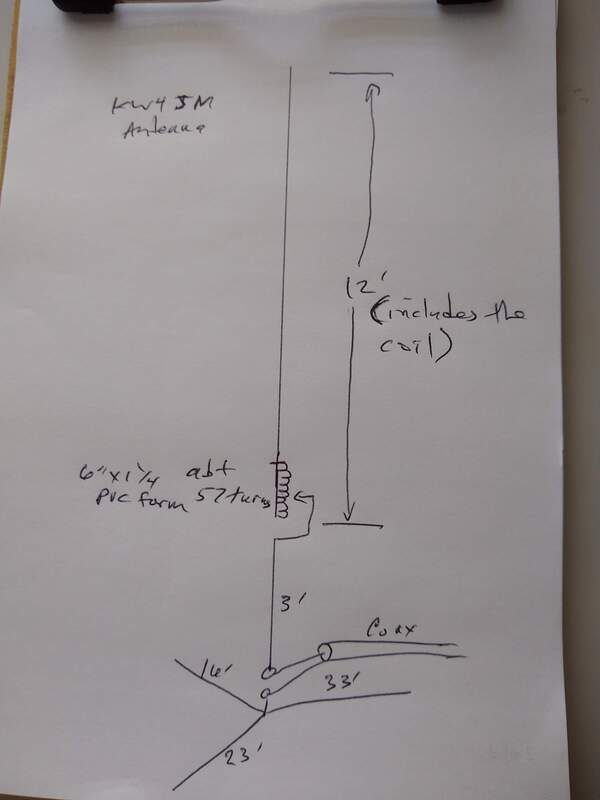
2020-02-05 A few days ago I watched a video by KW4JM describing his DIY No-Stick Buddy-Stick Antenna. We had a QSO a couple days earlier when Scott was a SOTA activator on a SUMMIT in the Western Carolina Mountains. His antenna seemed so simple and straight forward and so similar to the Wolf River Coils TIA and Pac 12 antennas I've been playing with that I had to give it a try. So this afternoon I built my version. Mine is essentially a 17 foot, 1/4 wavelength vertical on 20 meters with a center loading coil tapped for the lower frequency bands. The radiator above the coil is 12 feet long, the coil is about six inches long and the bottom section below the coil is about 4 feet long. All combined it is 17 feet long give or take a couple inches. The pictures pretty well describe it.
The schematic shows the overall antenna as KW4JM describes it. I made a small change based on my experience with the Wolf River Coils TIA antenna, and made the bottom section below the coil 4' long instead of 3' as his was. Another small change I made was the coil form. He wound the coil on a six inch piece of 1-1/4 PVC. That seemed heavy to me so I found a plastic plumbing pipe that normally attaches between a sink drain and the water trap below the kitchen sink. It is a bit smaller O.D. but much lighter weight. I wound 47 close-wound turns of 24 Gauge RCA Speaker wire and stopped, because my wire ran out! The entire thing is made using that 24 Gauge speaker wire. I had one of those BNC to banana plug adapters so used it like Scott did. I also cut the three radials 16', 23' and 33', also made of speaker wire. As Scott suggests I used a straight pin to poke through the insulation into the wire at various places to "tune" the loading coil.
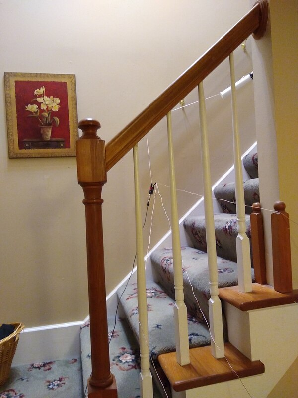
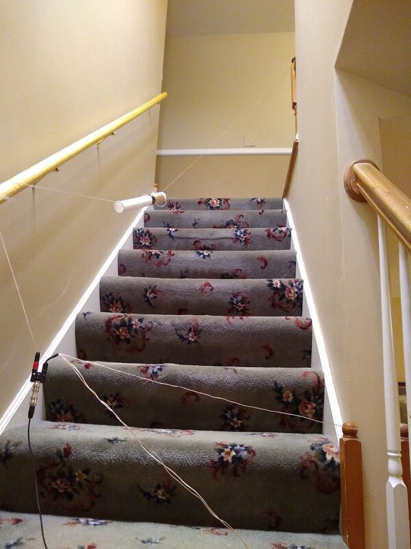
It was early evening when we finished dinner, and dark and cold outside. But I couldn't wait. So I strung it up in our stairway. I put a small nail in the door frame of the upstairs bathroom and looped the tip of the radiator around the nail, and then gently stretched the thing down the stairs and taped the bottom wire to the hand rail, letting the Connector dangle a foot or so below the rail. Then I strung the three radials around the house as best I could, connected a 25 foot piece of RG-174 feedline to my NanoVNA and turned it on. With the straight pin in the wire at the very top of the coil, to my surprise it was resonant in 20 meters, 14.070 to be exact with a very low SWR! Playing with the pin in different turns of the coil I discovered that 8 turns from the top resonated in the 30 meter band, 20 turns in 40 meters and 47 turns in the 60 meter band! And the SWR dips were clean and sharp!
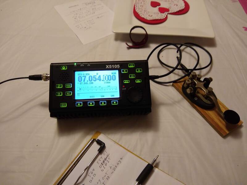
Being impatient, and with my wife out of the house helping with AWANA, the children's program at church, I quick got my xiegu x5105 and connected to the coax. With the pin in the 20th turn for 40 meters, I turned on the radio and amazing, there were signals, good ones! Again, unwilling to wait for one of the QSOs to end so I could call one of the stations, I tuned to 7.054 which was clear and called CQ. When I finished my second CQ call WB1GYZ, Bob, in CT answered. He was 589! Talk about being surprised! We had about a five minute QSO, solid all the way. When I told him what I was running, he responded "hi hi!" That's OK, I was laughing too. One QSO doesn't prove much but I'm happy tonight. Thanks, Scott, for the SOTA QSO a few days ago, and this great antenna idea! And thanks, Bob, for the motivating contact tonight!
I still have a little work to do on it before I declare it finished and ready for the cold, cruel world. I need to decide whether to lengthen the coil and try it on 80 meters, then I will cut the "sewer pipe" to length. I also need to add the little brass screw eyes to make the taps permanent. I don't think the stick pin is a good field idea! But I will be using it once the weather warms up a bit here in Wisconsin.
